Toyota 4Runner: Removal
REMOVAL
PROCEDURE
1. REMOVE SIDE STEP ASSEMBLY LH
.gif)
2. REMOVE STABILIZER CONTROL VALVE PROTECTOR
3. DRAIN SUSPENSION FLUID
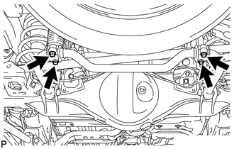
4. REMOVE REAR STABILIZER LOWER BRACKET
|
(a) Remove the 4 bolts and 2 rear stabilizer lower brackets. |
|
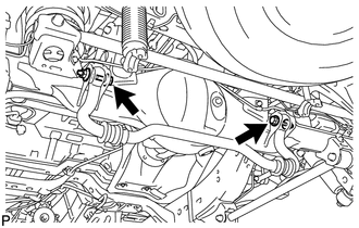
5. REMOVE REAR STABILIZER BAR SUB-ASSEMBLY
|
(a) Remove the 2 bolts, 2 nuts and rear stabilizer bar. NOTICE: Turn the bolts while holding the nuts. |
|
(b) Remove the 2 stabilizer bushes from the rear stabilizer bar.
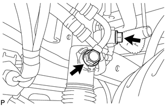
6. DISCONNECT REAR STABILIZER CONTROL TUBE ASSEMBLY
|
(a) Remove the 2 union bolts and 2 pressure port gaskets and disconnect the rear stabilizer control tube from the rear stabilizer control cylinder. |
|
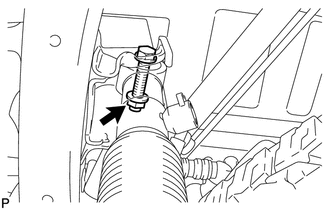
7. REMOVE REAR STABILIZER CONTROL CYLINDER
|
(a) Remove the bolt, nut and rear stabilizer control cylinder. NOTICE: Do not hold the rear stabilizer control cylinder by the cylinder boot. HINT: Turn the nut while holding the bolt. |
|
(b) Remove the 2 bleeder plug caps from the rear stabilizer control cylinder.
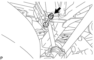
8. REMOVE REAR STABILIZER LINK ASSEMBLY
|
(a) Remove the bolt, nut and rear stabilizer link assembly. HINT: Turn the nut while holding the bolt. |
|
 Components
COMPONENTS
ILLUSTRATION
...
 Installation
INSTALLATION
PROCEDURE
1. INSTALL REAR STABILIZER LINK ASSEMBLY
(a) Install the rear stabilizer link assembly with the bolt and nut.
Torque:
100 N·m {1020 kgf·cm, 74 ft·lbf}
HINT:
Turn the ...
Other materials about Toyota 4Runner:
Image from Camera for Rear View Monitor is Abnormal
DESCRIPTION
The display signal from the rear television camera assembly transmits to the
radio and display receiver assembly.
WIRING DIAGRAM
PROCEDURE
1.
CHECK HARNESS AND CONNECTOR (RADIO AND DISPLAY RECEIVER ASSEMBLY - REAR
...
Audio Receiver Assembly Communication Stop Mode
DESCRIPTION
Detection Item
Symptom
Trouble Area
Audio Receiver Assembly Communication Stop Mode
Either condition is met:
"Display and Navigation (AVN1)" is not displayed on t ...
0.0067