Toyota 4Runner: Audio Receiver Assembly Communication Stop Mode
DESCRIPTION
|
Detection Item |
Symptom |
Trouble Area |
|---|---|---|
|
Audio Receiver Assembly Communication Stop Mode |
Either condition is met:
|
|
HINT:
For vehicles with a radio and display receiver assembly only.
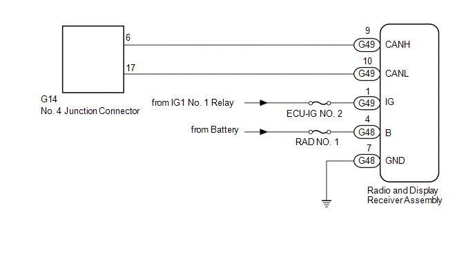
WIRING DIAGRAM
CAUTION / NOTICE / HINT
NOTICE:
Inspect the fuses for circuits related to this system before performing the following inspection procedure.
HINT:
Operating the ignition switch, any switches or any doors triggers related ECU and sensor communication with the CAN, which causes resistance variation.
PROCEDURE
|
1. |
DISCONNECT CABLE FROM NEGATIVE BATTERY TERMINAL |
(a) Disconnect the cable from the negative (-) battery terminal before measuring the resistances of the main wire and branch wire.
CAUTION:
Wait at least 90 seconds after disconnecting the cable from the negative (-) battery terminal to disable the SRS system.
NOTICE:
When disconnecting the cable, some systems need to be initialized after the cable
is reconnected (See page .gif) ).
).
|
.gif)
|
2. |
CHECK FOR OPEN IN CAN BUS WIRE (RADIO AND DISPLAY RECEIVER ASSEMBLY BRANCH WIRE) |
|
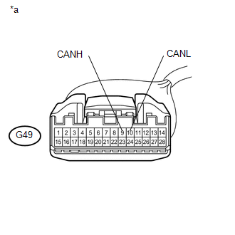
(a) Disconnect the G49 radio and display receiver assembly connector. |
|
(b) Measure the resistance according to the value(s) in the table below.
Standard Resistance:
|
Tester Connection |
Switch Condition |
Specified Condition |
|---|---|---|
|
G49-9 (CANH) - G49-10 (CANL) |
Ignition switch off |
54 to 69 Ω |
|
*a |
Front view of wire harness connector (to Radio and Display Receiver Assembly) |
| NG | .gif) |
REPAIR OR REPLACE RADIO AND DISPLAY RECEIVER ASSEMBLY BRANCH WIRE OR CONNECTOR (CANH, CANL) |
|
|
3. |
CHECK HARNESS AND CONNECTOR (RADIO AND DISPLAY RECEIVER ASSEMBLY - BATTERY AND BODY GROUND) |
|
(a) Connect the cable to the negative (-) battery terminal. NOTICE: When disconnecting the cable, some systems need to be initialized after
the cable is reconnected (See page |
|
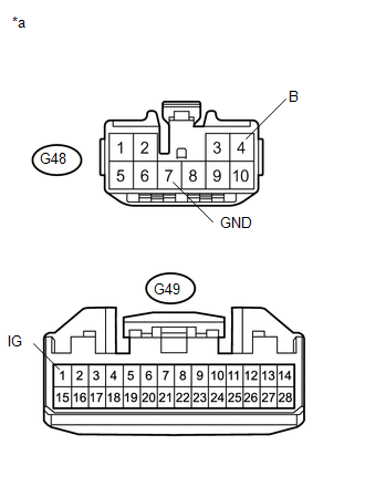
(b) Disconnect the G48 and G49 radio and display receiver assembly connectors.
(c) Measure the resistance according to the value(s) in the table below.
Standard Resistance:
|
Tester Connection |
Condition |
Specified Condition |
|---|---|---|
|
G48-7 (GND) - Body ground |
Always |
Below 1 Ω |
(d) Measure the voltage according to the value(s) in the table below.
Standard Voltage:
|
Tester Connection |
Condition |
Specified Condition |
|---|---|---|
|
G49-1 (IG) - Body ground |
Ignition switch ON |
11 to 14 V |
|
G48-4 (B) - Body ground |
Always |
11 to 14 V |
|
*a |
Front view of wire harness connector (to Radio and Display Receiver Assembly) |
| OK | |
REPLACE RADIO AND DISPLAY RECEIVER ASSEMBLY |
| NG | |
REPAIR OR REPLACE HARNESS OR CONNECTOR |
 Navigation Receiver Assembly Communication Stop Mode
DESCRIPTION
Detection Item
Symptom
Trouble Area
Navigation Receiver Assembly Communication Stop Mode
Either condition is met:
...
 Open in CAN Main Wire
DESCRIPTION
There may be an open circuit in the CAN main wire and/or DLC3 branch wire when
the resistance between terminals 6 (CANH) and 14 (CANL) of the DLC3 is 69 Ω or higher.
Sympto ...
Other materials about Toyota 4Runner:
Rear Power Outlet Socket
Components
COMPONENTS
ILLUSTRATION
Removal
REMOVAL
PROCEDURE
1. REMOVE POWER OUTLET SOCKET BEZEL (w/o Smart Key System)
(a) Put protective tape around the power outlet socket bezel.
Text in Illustration
*1
...
Reassembly
REASSEMBLY
PROCEDURE
1. INSTALL STEERING RACK END SUB-ASSEMBLY
(a) Temporarily install the 2 steering rack ends to the steering rack.
(b) Fill up the ball joints of the steering rack ends with MP grease.
(c) Using SST, install the steering rack ...
0.0067