Toyota 4Runner: Removal
REMOVAL
PROCEDURE
1. REMOVE REAR AXLE SHAFT RH
(a) Remove the rear axle shaft RH (See page .gif)
).
2. REMOVE REAR AXLE SHAFT LH
HINT:
Use the same procedure described for the RH side.
3. REMOVE PROPELLER SHAFT ASSEMBLY
(a) Remove the propeller shaft assembly (See page
).
4. REMOVE REAR DIFFERENTIAL CARRIER ASSEMBLY
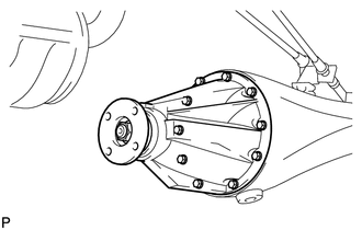
(a) Remove the 10 nuts and 10 washers, differential carrier.
NOTICE:
Be careful not to damage the contact surfaces.
5. REMOVE REAR DIFFERENTIAL CARRIER GASKET
 Components
COMPONENTS
ILLUSTRATION
ILLUSTRATION
ILLUSTRATION
ILLUSTRATION
...
 Disassembly
DISASSEMBLY
PROCEDURE
1. FIX REAR DIFFERENTIAL CARRIER ASSEMBLY IN PLACE
2. INSPECT RUNOUT OF REAR DRIVE PINION COMPANION FLANGE SUB-ASSEMBLY REAR
(a) Using a dial indicator, measure the runou ...
Other materials about Toyota 4Runner:
Problem Symptoms Table
PROBLEM SYMPTOMS TABLE
HINT:
Use the table below to help determine the cause of problem symptoms.
If multiple suspected areas are listed, the potential causes of the symptoms
are listed in order of probability in the "Suspected Area" ...
VSC OFF Indicator Light Remains ON
DESCRIPTION
Operation of the VSC OFF switch changes the vehicle between normal mode, TRAC
OFF mode*1 (AUTO LSD mode*2) and VSC OFF mode. During normal mode, pressing the
VSC OFF switch for a short amount of time changes vehicle to TRAC OFF mode*1 (AUTO
...
0.0184