Toyota 4Runner: Rocker Panel Moulding
Components
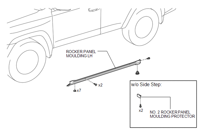
COMPONENTS
ILLUSTRATION
Removal
REMOVAL
CAUTION / NOTICE / HINT
HINT:
- Use the same procedure for both the RH and LH sides.
- The procedure listed below is for the LH side.
PROCEDURE
1. REMOVE SIDE STEP ASSEMBLY LH (w/ Side Step)
(See page .gif) )
)
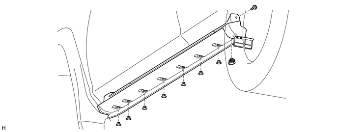
2. REMOVE ROCKER PANEL MOULDING LH
(a) Remove the 7 retainers, clip and screw.
(b) Put protective tape around the rocker panel moulding LH.
(c) Remove the 2 screws.
(d) Detach the 7 clips to remove the rocker panel moulding LH.
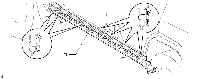 Text in Illustration
|
*1 |
Protective Tape |
- |
- |
3. REMOVE NO. 2 ROCKER PANEL MOULDING PROTECTOR (w/o Side Step)
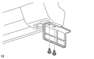
(a) Remove the 2 screws and No. 2 rocker panel moulding protector.
Installation
INSTALLATION
CAUTION / NOTICE / HINT
HINT:
- Use the same procedure for both the RH and LH sides.
- The procedure listed below is for the LH side.
PROCEDURE
1. INSTALL NO. 2 ROCKER PANEL MOULDING PROTECTOR (w/o Side Step)
(a) Install the No. 2 rocker panel moulding protector with the 2 screws.
2. INSTALL ROCKER PANEL MOULDING LH
(a) Attach the 7 clips to install the rocker panel moulding LH.
(b) Install the 3 screws.
(c) Attach the 7 retainers and clip.
3. INSTALL SIDE STEP ASSEMBLY LH (w/ Side Step)
(See page .gif) )
)
 Installation
INSTALLATION
CAUTION / NOTICE / HINT
HINT:
A bolt without a torque specification is shown in the standard bolt chart (See
page ).
PROCEDURE
1. INSTALL REAR NO. 2 SPOILER CLIP
HINT:
Use the s ...
 Rocker Panel Moulding(w/ Intuitive Parking Assist System)
Components
COMPONENTS
ILLUSTRATION
Installation
INSTALLATION
CAUTION / NOTICE / HINT
HINT:
Use the same procedure for both the RH and LH sides.
The procedure listed below is f ...
Other materials about Toyota 4Runner:
Ignition Key Cylinder Light
Components
COMPONENTS
ILLUSTRATION
Removal
REMOVAL
PROCEDURE
1. REMOVE NO. 2 SWITCH HOLE BASE
2. REMOVE LOWER INSTRUMENT PANEL FINISH PANEL ASSEMBLY
3. REMOVE INSTRUMENT CLUSTER FINISH PANEL SUB-ASSEMBLY
4. REMOVE LOWER STEERING COLUMN ...
Installation
INSTALLATION
CAUTION / NOTICE / HINT
HINT:
Use the same procedure for the RH and LH sides.
The procedure listed below is for the LH side.
A bolt without a torque specification is shown in the standard bolt
chart (See page ).
PROC ...
0.0263