Toyota 4Runner: Rocker Panel Moulding(w/ Intuitive Parking Assist System)
Components
COMPONENTS
ILLUSTRATION
Installation
INSTALLATION
CAUTION / NOTICE / HINT
HINT:
- Use the same procedure for both the RH and LH sides.
- The procedure listed below is for the LH side.
PROCEDURE
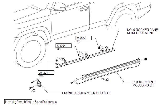
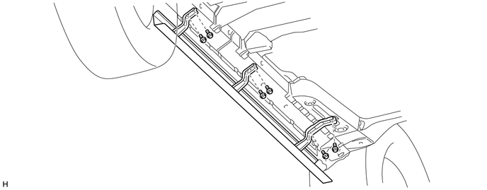
1. INSTALL NO. 6 ROCKER PANEL REINFORCEMENT
(a) Install the No. 6 rocker panel reinforcement with the 6 bolts.
Torque:
20 N·m {204 kgf·cm, 15 ft·lbf}
2. INSTALL ROCKER PANEL MOULDING LH
(a) Attach the 15 clips to install the rocker panel moulding LH.
(b) Install the 4 screws.
3. INSTALL FRONT FENDER MUDGUARD LH
.gif)
Removal
REMOVAL
CAUTION / NOTICE / HINT
HINT:
- Use the same procedure for both the RH and LH sides.
- The procedure listed below is for the LH side.
PROCEDURE
1. REMOVE FRONT FENDER MUDGUARD LH
.gif)
2. REMOVE ROCKER PANEL MOULDING LH
(a) Put protective tape around the rocker panel moulding LH.
(b) Remove the 4 screws.
(c) Detach the 15 clips to remove the rocker panel moulding LH.
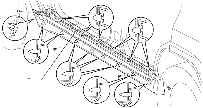 Text in Illustration
|
*1 |
Protective Tape |
- |
- |
3. REMOVE NO. 6 ROCKER PANEL REINFORCEMENT
(a) Remove the 6 bolts and No. 6 rocker panel reinforcement.
 Rocker Panel Moulding
Components
COMPONENTS
ILLUSTRATION
Removal
REMOVAL
CAUTION / NOTICE / HINT
HINT:
Use the same procedure for both the RH and LH sides.
The procedure listed below is for the LH ...

Other materials about Toyota 4Runner:
System Description
SYSTEM DESCRIPTION
1. WIRELESS DOOR LOCK CONTROL SYSTEM DESCRIPTION
(a) This system locks/unlocks the vehicle doors remotely. The wireless control
system has the following features:
The door control receiver performs the code identification procedu ...
Components
COMPONENTS
ILLUSTRATION
ILLUSTRATION
ILLUSTRATION
ILLUSTRATION
ILLUSTRATION
...
0.0241