Toyota 4Runner: Room Light(for Rear)
Components
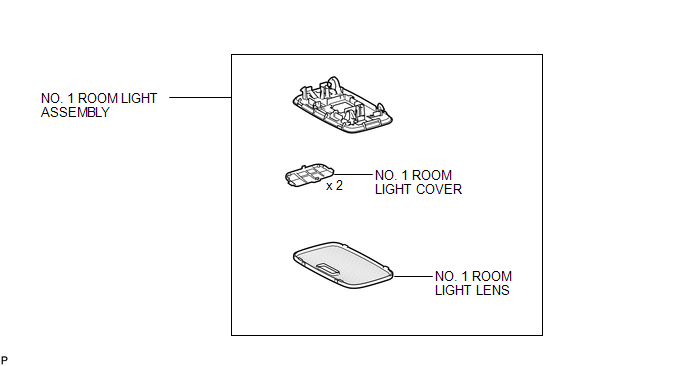
COMPONENTS
ILLUSTRATION
Installation
INSTALLATION
PROCEDURE
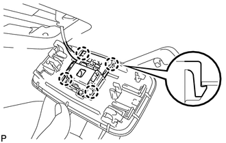
1. INSTALL NO. 1 ROOM LIGHT ASSEMBLY
|
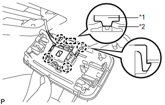
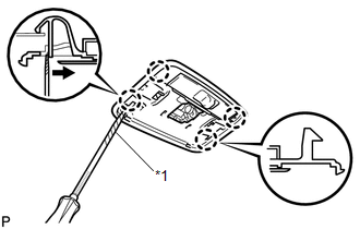
(a) Align the switch parts as shown in the illustration and attach the 4 claws to install the room light switch base to the No. 1 room light assembly. Text in Illustration
|
|
|
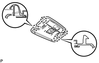
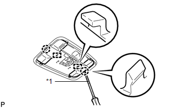
(b) Attach the 4 claws to install the No. 1 room light assembly. |
|
|
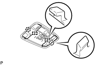
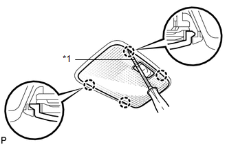
(c) Attach the 2 claws and 2 guides to install the 2 No. 1 room light covers. |
|
|
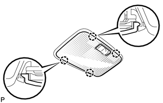
(d) Attach the 4 claws to install the No. 1 room light lens. |
|
Removal
REMOVAL
PROCEDURE
1. REMOVE NO. 1 ROOM LIGHT ASSEMBLY
|
(a) Using a screwdriver, detach the 4 claws and remove the No. 1 room light lens. HINT: Tape the screwdriver tip before use. Text in Illustration
|
|
|
(b) Using a screwdriver, detach the 2 claws and 2 guides and remove the 2 No. 1 room light covers. HINT: Tape the screwdriver tip before use. Text in Illustration
|
|
|
(c) Using a screwdriver, detach the 4 claws and disconnect the No. 1 room light assembly as shown in the illustration. HINT: Tape the screwdriver tip before use. Text in Illustration
|
|
|
(d) Using a screwdriver, detach the 4 claws and disconnect the room light switch base from the No. 1 room light assembly. |
|
 Room Light(for Front)
Components
COMPONENTS
ILLUSTRATION
Inspection
INSPECTION
PROCEDURE
1. INSPECT MAP LIGHT ASSEMBLY
(a) Measure the resistance according to the value(s) in the table below.
Sta ...

Other materials about Toyota 4Runner:
XM Tuner Malfunction (B15BA)
DESCRIPTION
These DTCs are stored when a malfunction occurs in the stereo component tuner
assembly.
DTC Code
DTC Detection Condition
Trouble Area
B15BA
When either of the conditions below is met: ...
Disc cannot be Ejected
CAUTION / NOTICE / HINT
NOTICE:
After replacing the navigation receiver assembly of vehicles subscribed to pay-type
satellite radio broadcasts, XM radio ID registration is necessary.
PROCEDURE
1.
CHECK OPERATION
(a) Press ...
0.0269