Toyota 4Runner: Room Light(for Front)
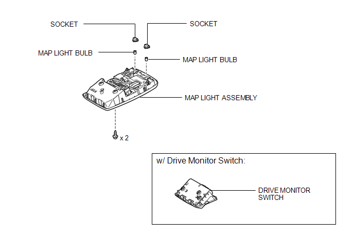
Components
COMPONENTS
ILLUSTRATION
Inspection
INSPECTION
PROCEDURE
1. INSPECT MAP LIGHT ASSEMBLY
|
(a) Measure the resistance according to the value(s) in the table below. Standard Resistance:
|
|
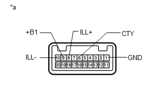
(b) Apply battery voltage to the connector and check the LED illumination.
OK:
|
Condition |
Specified Condition |
|---|---|
|
Battery positive (+) → Terminal 8 (ILL+) Battery negative (-) → Terminal 10 (ILL-) |
LED illuminates |
|
*a |
Component without harness connected (Map Light Assembly) |
If the result is not as specified, replace the map light assembly.
Removal
REMOVAL
PROCEDURE
1. REMOVE DRIVE MONITOR SWITCH (w/ Drive Monitor Switch)
|
(a) Detach the 4 claws to remove the drive monitor switch. |
|
.png)
(b) Disconnect the connector.
2. REMOVE MAP LIGHT ASSEMBLY
(a) Open the cover (w/o Drive Monitor Switch).
|
(b) Remove the 2 screws. |
|
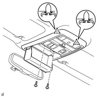
(c) Detach the 2 clips to remove the map light assembly.
(d) Disconnect the connector.
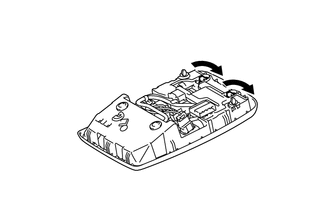
3. REMOVE MAP LIGHT BULB
|
(a) Turn the 2 sockets in the direction indicated by the arrows to remove them. |
|
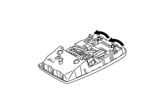
(b) Remove the 2 map light bulbs from the sockets.
Installation
INSTALLATION
PROCEDURE
1. INSTALL MAP LIGHT BULB
(a) Install the 2 map light bulbs to the sockets.
|
(b) Turn the 2 sockets in the direction indicated by the arrows to install them. |
|
2. INSTALL MAP LIGHT ASSEMBLY
(a) Connect the connector.
(b) Attach the 2 clips to install the map light assembly.
(c) Install the 2 screws.
(d) Close the cover (w/o Drive Monitor Switch).
3. INSTALL DRIVE MONITOR SWITCH (w/ Drive Monitor Switch)
(a) Connect the connector.
(b) Attach the 4 claws to install the drive monitor switch.
 Relay
Relay
On-vehicle Inspection
ON-VEHICLE INSPECTION
PROCEDURE
1. INSPECT DOME RELAY
(a) Measure the resistance according to the value(s) in the table below.
Standard Resistance:
...
 Room Light(for Rear)
Components
COMPONENTS
ILLUSTRATION
Installation
INSTALLATION
PROCEDURE
1. INSTALL NO. 1 ROOM LIGHT ASSEMBLY
(a) Align the switch parts as shown in the illustration and attach t ...
Other materials about Toyota 4Runner:
Installation
INSTALLATION
PROCEDURE
1. INSTALL RACK AND PINION POWER STEERING GEAR ASSEMBLY
(a) Insert the power steering gear assembly into the vehicle in the order shown
in the illustration.
Install in this Direction (1)
In ...
If you cannot operate back door opener
If the back door opener does not operate, there may be a problem with the
back door opener system. Have the vehicle inspected by your Toyota dealer
immediately.
The following steps may be used as an emergency measure to ensure that the
back door can be ...
0.0071