Toyota 4Runner: Side Auto Step ECU Power Source Circuit
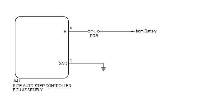
WIRING DIAGRAM
CAUTION / NOTICE / HINT
NOTICE:
Inspect the fuses for circuits related to this system before performing the following inspection procedure.
PROCEDURE
|
1. |
CHECK HARNESS AND CONNECTOR (SIDE AUTO STEP CONTROLLER ECU - BODY GROUND) |
(a) Disconnect the A41 side auto step controller ECU assembly connector.
(b) Measure the resistance according to the value(s) in the table below.
Standard Resistance:
|
Tester Connection |
Condition |
Specified Condition |
|---|---|---|
|
A41-1 (GND) - Body ground |
Always |
Below 1 Ω |
| NG | .gif) |
REPAIR OR REPLACE HARNESS OR CONNECTOR |
|
.gif)
|
2. |
CHECK HARNESS AND CONNECTOR (POWER SOURCE) |
(a) Measure the voltage according to the value(s) in the table below.
Standard Voltage:
|
Tester Connection |
Condition |
Specified Condition |
|---|---|---|
|
A41-4 (B) - Body ground |
Always |
11 to 14 V |
| A | |
PROCEED TO NEXT SUSPECTED AREA SHOWN IN PROBLEM SYMPTOMS TABLE |
| B | |
REPAIR OR REPLACE HARNESS OR CONNECTOR |
 Short to GND in Motor LH Circuit (21,23)
DESCRIPTION
When there is a short to GND in the side auto step motor circuit, the side auto
step controller ECU assembly does not operate the automatic running board.
DTC No.
...
 Side Auto Step Switch Circuit
DESCRIPTION
The side auto step controller ECU assembly receives the door open/closed signal
from each door courtesy light switch via the side auto step switch assembly.
WIRING DIAGRAM
CAUTION / ...
Other materials about Toyota 4Runner:
Power Supply Drive Circuit (C1257)
DESCRIPTION
The motor relay (semiconductor relay) is built into the master cylinder solenoid
and drives the pump motor based on a signal from the skid control ECU.
DTC Code
DTC Detection Condition
Trouble Area
...
Registration
REGISTRATION
PROCEDURE
1. BEFORE REGISTRATION
NOTICE:
The transmitter ID is written on the tire pressure warning valve and transmitter.
It is not possible to read the transmitter ID after installing the tire onto the
wheel. Therefore, make a note of th ...
0.0235