Toyota 4Runner: Side Auto Step Switch Circuit
DESCRIPTION
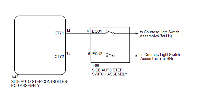
The side auto step controller ECU assembly receives the door open/closed signal from each door courtesy light switch via the side auto step switch assembly.
WIRING DIAGRAM
CAUTION / NOTICE / HINT
HINT:
Inspection should be performed on the door courtesy switch circuit on the side where the automatic running board is malfunctioning.
PROCEDURE
|
1. |
CHECK HARNESS AND CONNECTOR (SIDE AUTO STEP SWITCH - SIDE AUTO STEP CONTROLLER ECU) |
(a) Disconnect the F90 side auto step switch assembly connector.
(b) Disconnect the A42 side auto step controller ECU assembly connector.
(c) Measure the resistance according to the value(s) in the table below.
Standard Resistance (Check for Open):
for LH|
Tester Connection |
Condition |
Specified Condition |
|---|---|---|
|
F90-4 (ECU1) - A42-14 (CTY1) |
Always |
Below 1 Ω |
|
Tester Connection |
Condition |
Specified Condition |
|---|---|---|
|
F90-6 (ECU2) - A42-13 (CTY2) |
Always |
Below 1 Ω |
Standard Resistance (Check for Short):
for LH|
Tester Connection |
Condition |
Specified Condition |
|---|---|---|
|
A42-14 (CTY1) - Body ground |
Always |
10 kΩ or higher |
|
Tester Connection |
Condition |
Specified Condition |
|---|---|---|
|
A42-13 (CTY2) - Body ground |
Always |
10 kΩ or higher |
| OK | .gif) |
PROCEED TO NEXT SUSPECTED AREA SHOWN IN PROBLEM SYMPTOMS TABLE |
| NG | |
REPAIR OR REPLACE HARNESS OR CONNECTOR |
 Side Auto Step ECU Power Source Circuit
WIRING DIAGRAM
CAUTION / NOTICE / HINT
NOTICE:
Inspect the fuses for circuits related to this system before performing the following
inspection procedure.
PROCEDURE
1.
...
 Door Courtesy Switch Circuit
DESCRIPTION
The side auto step controller ECU assembly receives the door open/closed signal
from each door courtesy light switch via the side auto step switch assembly.
WIRING DIAGRAM
CAUTION / ...
Other materials about Toyota 4Runner:
Mute Signal Circuit between Stereo Component Amplifier and Telematics Transceiver
DESCRIPTION
The DCM (telematics transceiver) sends a mute signal to the stereo component
amplifier assembly.
The stereo component amplifier assembly controls the volume according to the
mute signal from the DCM (telematics transceiver).
WIRING DIAGRAM
...
System Diagram
SYSTEM DIAGRAM
1. DOOR BUS LINES
2. CERTIFICATION BUS LINES (w/ Smart Key System)
3. AIR CONDITIONING BUS LINES
4. SUB-LIN BUS LINES
5. DRIVE MONITOR SWITCH BUS LINES (w/ CRAWL Control)
...
0.0254