Toyota 4Runner: Side Turn Signal Light Assembly
Components
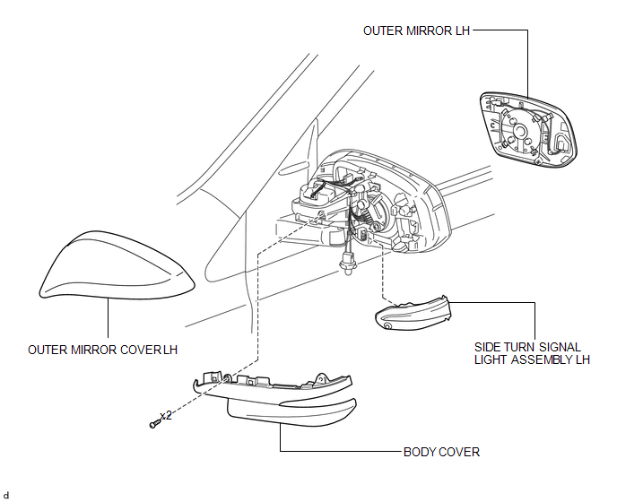
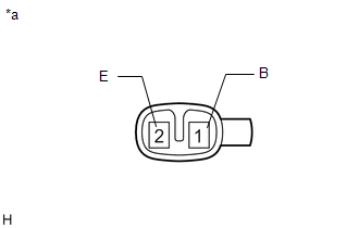
COMPONENTS
ILLUSTRATION
Removal
REMOVAL
CAUTION / NOTICE / HINT
HINT:
- Use the same procedure for both the RH and LH sides.
- The procedure listed below is for the LH side.
PROCEDURE
1. REMOVE OUTER MIRROR LH
.gif)
2. REMOVE OUTER MIRROR COVER LH
3. REMOVE SIDE TURN SIGNAL LIGHT ASSEMBLY LH
(a) Retract the outer rear view mirror assembly LH.
|
(b) Remove the 2 screws. |
|
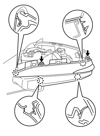
(c) Detach the 4 claws.
|
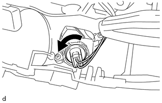
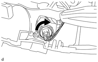
(d) Turn the socket in the direction indicated by the arrow to remove the body cover. |
|
|
(e) Detach the 2 claws. |
|
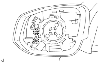
(f) Disconnect the connector and remove the side turn signal light assembly LH.
Inspection
INSPECTION
CAUTION / NOTICE / HINT
HINT:
- Use the same procedure for both the RH and LH sides.
- The procedure listed below is for the LH side.
PROCEDURE
1. REMOVE SIDE TURN SIGNAL LIGHT ASSEMBLY LH
|
(a) Apply battery voltage to the connector and check the light illumination condition. OK:
If the result is not as specified, replace the side turn signal light assembly LH. |
|
Installation
INSTALLATION
CAUTION / NOTICE / HINT
HINT:
- Use the same procedure for both the RH and LH sides.
- The procedure listed below is for the LH side.
PROCEDURE
1. INSTALL SIDE TURN SIGNAL LIGHT ASSEMBLY LH
(a) Connect the connector.
(b) Attach the 2 claws to install the side turn signal light assembly LH.
(c) Retract the outer rear view mirror assembly LH.
|
(d) Turn the socket in the direction indicated by the arrow to install it. |
|
(e) Attach the 4 claws to install the body cover.
(f) Install the 2 screws.
2. INSTALL OUTER MIRROR COVER LH
.gif)
3. INSTALL OUTER MIRROR LH
 Relay
Relay
On-vehicle Inspection
ON-VEHICLE INSPECTION
PROCEDURE
1. REMOVE HEADLIGHT RELAY
(a) Remove the headlight relay from the engine room relay box.
...
 Stop Light Switch
Components
COMPONENTS
ILLUSTRATION
On-vehicle Inspection
ON-VEHICLE INSPECTION
PROCEDURE
1. INSPECT STOP LIGHT SWITCH ASSEMBLY
(a) Disconnect the connector from the stop light ...
Other materials about Toyota 4Runner:
Low Power Supply Voltage Malfunction (C1241)
DESCRIPTION
If the voltage supplied to the IG1 terminal is within the DTC detection range
due to malfunctions in components such as the battery and generator circuit, this
DTC is stored.
DTC Code
DTC Detection Condition
T ...
Removal
REMOVAL
PROCEDURE
1. DISCONNECT CABLE FROM NEGATIVE BATTERY TERMINAL
CAUTION:
Wait at least 90 seconds after disconnecting the cable from the negative (-)
battery terminal to disable the SRS system.
NOTICE:
When disconnecting the cable, some systems ne ...
0.0085