Toyota 4Runner: Steering Angle Sensor Communication Stop Mode
DESCRIPTION
|
Detection Item |
Symptom |
Trouble Area |
|---|---|---|
|
Steering Angle Sensor Communication Stop Mode |
Either condition is met:
|
|
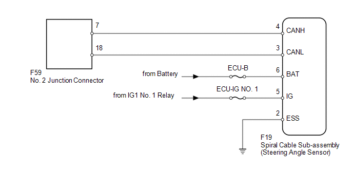
WIRING DIAGRAM
CAUTION / NOTICE / HINT
NOTICE:
Inspect the fuses for circuits related to this system before performing the following inspection procedure.
HINT:
Operating the ignition switch, any switches or any doors triggers related ECU and sensor communication with the CAN, which causes resistance variation.
PROCEDURE
|
1. |
DISCONNECT CABLE FROM NEGATIVE BATTERY TERMINAL |
(a) Disconnect the cable from the negative (-) battery terminal before measuring the resistances of the main wire and branch wire.
CAUTION:
Wait at least 90 seconds after disconnecting the cable from the negative (-) battery terminal to disable the SRS system.
NOTICE:
When disconnecting the cable, some systems need to be initialized after the cable
is reconnected (See page .gif) ).
).
|
.gif)
|
2. |
CHECK FOR OPEN IN CAN BUS WIRE (SPIRAL CABLE SUB-ASSEMBLY BRANCH WIRE) |
|
(a) Disconnect the F19 spiral cable sub-assembly (steering angle sensor) connector. |
|
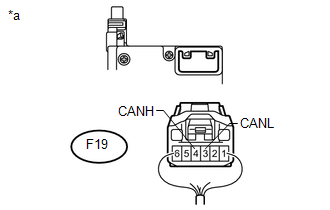
(b) Measure the resistance according to the value(s) in the table below.
Standard Resistance:
|
Tester Connection |
Switch Condition |
Specified Condition |
|---|---|---|
|
F19-4 (CANH) - F19-3 (CANL) |
Ignition switch off |
54 to 69 Ω |
|
*a |
Rear view of wire harness connector (to Spiral Cable Sub-assembly [Steering Angle Sensor]) |
| NG | .gif) |
REPAIR OR REPLACE SPIRAL CABLE SUB-ASSEMBLY BRANCH WIRE OR CONNECTOR (CANH, CANL) |
|
|
3. |
CHECK HARNESS AND CONNECTOR (SPIRAL CABLE SUB-ASSEMBLY - BATTERY AND BODY GROUND) |
|
(a) Connect the cable to the negative (-) battery terminal. NOTICE: When disconnecting the cable, some systems need to be initialized after
the cable is reconnected (See page |
|
(b) Measure the resistance according to the value(s) in the table below.
Standard Resistance:
|
Tester Connection |
Condition |
Specified Condition |
|---|---|---|
|
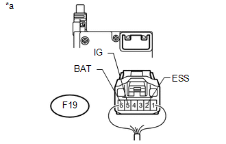
F19-2 (ESS) - Body ground |
Always |
Below 1 Ω |
(c) Measure the voltage according to the value(s) in the table below.
Standard Voltage:
|
Tester Connection |
Switch Condition |
Specified Condition |
|---|---|---|
|
F19-6 (BAT) - Body ground |
Always |
11 to 14 V |
|
F19-5 (IG) - Body ground |
Ignition switch ON |
11 to 14 V |
|
*a |
Rear view of wire harness connector (to Spiral Cable Sub-assembly [Steering Angle Sensor]) |
| OK | |
REPLACE SPIRAL CABLE SUB-ASSEMBLY |
| NG | |
REPAIR OR REPLACE HARNESS OR CONNECTOR |
 Power Steering ECU Communication Stop Mode
DESCRIPTION
Detection Item
Symptom
Trouble Area
Power Steering ECU Communication Stop Mode
Either condition is met:
"PP ...
 Yaw Rate Sensor Communication Stop Mode
DESCRIPTION
Detection Item
Symptom
Trouble Area
Yaw Rate Sensor Communication Stop Mode
Either condition is met:
"Yaw R ...
Other materials about Toyota 4Runner:
Hood Support
Components
COMPONENTS
ILLUSTRATION
Removal
REMOVAL
CAUTION / NOTICE / HINT
HINT:
Use the same procedure for the RH and LH sides.
The procedure listed below is for the LH side.
PROCEDURE
1. REMOVE HOOD SUPPORT ASSEMBLY LH
NO ...
Rear Brake Flexible Hose
Components
COMPONENTS
ILLUSTRATION
ILLUSTRATION
Removal
REMOVAL
CAUTION / NOTICE / HINT
HINT:
Use the same procedure for the RH and LH sides.
The procedure listed below is for the LH side.
PROCEDURE
1. REMOVE REAR WHEEL
2. ...
0.007