Toyota 4Runner: Steering Lock Position Signal Circuit Malfunction (B2285)
DESCRIPTION
The power management control ECU and steering lock actuator (steering lock ECU) are connected by a cable and the LIN communication line. This DTC is stored when the steering lock position signal information from the cable and the steering lock position signal information from the LIN communication line are inconsistent.
HINT:
When the power management control ECU is replaced with a new one and the cable is connected to the negative (-) battery terminal, the power source mode is reset to on (IG). When the battery is removed and reinstalled, the power source mode that was selected when the battery was removed is restored.
|
DTC Code |
DTC Detection Condition |
Trouble Area |
|---|---|---|
|
B2285 |
The steering lock position signal information from the cable and the steering lock position signal information from the LIN communication line are inconsistent. |
|
WIRING DIAGRAM
.png)
CAUTION / NOTICE / HINT
NOTICE:
- When using the Techstream with the engine switch off to troubleshoot: Connect the Techstream to the vehicle and turn a courtesy light switch on and off at 1.5 second intervals until communication between the Techstream and vehicle begins.
- Before performing the inspection, check that there are no problems related to the CAN communication system and LIN communication system.
- Inspect the fuses for circuits related to this system before performing the following inspection procedure.
- After replacing the steering lock actuator assembly (steering lock ECU),
perform key ID code registration (See page
.gif) ).
).
PROCEDURE
|
1. |
CHECK FOR DTC (LIN COMMUNICATION SYSTEM) |
(a) Clear the DTCs (See page ).
(b) Check for DTCs (See page ).
OK:
LIN communication system DTCs B2287 and B2785 are not output simultaneously.
| NG | .gif) |
GO TO DTC B2287 |
|
.gif)
|
2. |
CHECK HARNESS AND CONNECTOR (BATTERY - POWER MANAGEMENT CONTROL ECU) |
| NG | |
REPAIR OR REPLACE HARNESS OR CONNECTOR |
|
|
3. |
CHECK HARNESS AND CONNECTOR (POWER MANAGEMENT CONTROL ECU - BODY GROUND) |
| NG | |
REPAIR OR REPLACE HARNESS OR CONNECTOR |
|
|
4. |
INSPECT STEERING LOCK ACTUATOR ASSEMBLY (STEERING LOCK ECU) |
|
(a) Measure the resistance according to the value(s) in the table below. Standard Resistance:
|
|
| NG | |
REPLACE STEERING LOCK ACTUATOR ASSEMBLY (STEERING LOCK ECU) |
|
|
5. |
CHECK HARNESS AND CONNECTOR (POWER MANAGEMENT CONTROL ECU - STEERING LOCK ECU) |
(a) Disconnect the F80 power management control ECU connector.
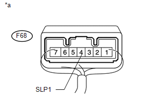
(b) Disconnect the F68 steering lock ECU connector.
(c) Measure the resistance according to the value(s) in the table below.
Standard Resistance:
|
Tester Connection |
Condition |
Specified Condition |
|---|---|---|
|
F80-3 (SLP) - F68-4 (SLP1) |
Always |
Below 1 Ω |
|
F80-3 (SLP) or F68-4 (SLP1) - Body ground |
Always |
10 kΩ or higher |
| NG | |
REPAIR OR REPLACE HARNESS OR CONNECTOR |
|
|
6. |
READ VALUE USING TECHSTREAM (STEERING UNLOCK SWITCH) |
(a) Connect the Techstream to the DLC3.
(b) Turn the engine switch on (IG).
(c) Turn the Techstream on.
(d) Enter the following menus: Body Electrical / Power Source Control / Data List.
(e) According to the display on the Techstream, read the Data List.
Power Source Control|
Tester Display |
Measurement Item/Range |
Normal Condition |
Diagnostic Note |
|---|---|---|---|
|
Steering Unlock Switch |
Steering lock condition / ON or OFF |
ON: Steering lock released (Engine switch on [ACC]) OFF: Steering lock locked (Engine switch off) |
- |
OK:
ON (steering lock released) or OFF (steering lock locked) appears on the screen according to the steering lock condition.
| OK | |
REPLACE STEERING LOCK ACTUATOR ASSEMBLY (STEERING LOCK ECU) |
| NG | |
REPLACE POWER MANAGEMENT CONTROL ECU |
 Diagnostic Trouble Code Chart
DIAGNOSTIC TROUBLE CODE CHART
HINT:
If a trouble code is output during the DTC check, inspect the trouble areas listed
for that code. For details of the code, refer to the "See page" bel ...
 Runnable Signal Malfunction (B2286,P0335)
DESCRIPTION
The power management control ECU and ECM are connected by a cable and the CAN
communication lines. These DTCs are stored when the crankshaft position sensor signal
information from th ...
Other materials about Toyota 4Runner:
Removal
REMOVAL
CAUTION / NOTICE / HINT
HINT:
Use the same procedure for the RH and LH sides.
The procedure listed below is for the LH side.
PROCEDURE
1. REMOVE ROOF HEADLINING ASSEMBLY
(a) Remove the roof headlining assembly (See page
).
2. ...
Installation
INSTALLATION
PROCEDURE
1. INSTALL BRAKE BOOSTER GASKET
(a) Install a new brake booster gasket to the hydraulic brake booster.
2. INSTALL HYDRAULIC BRAKE BOOSTER ASSEMBLY
(a) Install the hydraulic brake booster assembly with the 4 nuts.
Torque:
14 N·m ...
0.0128