Toyota 4Runner: System Diagram
SYSTEM DIAGRAM
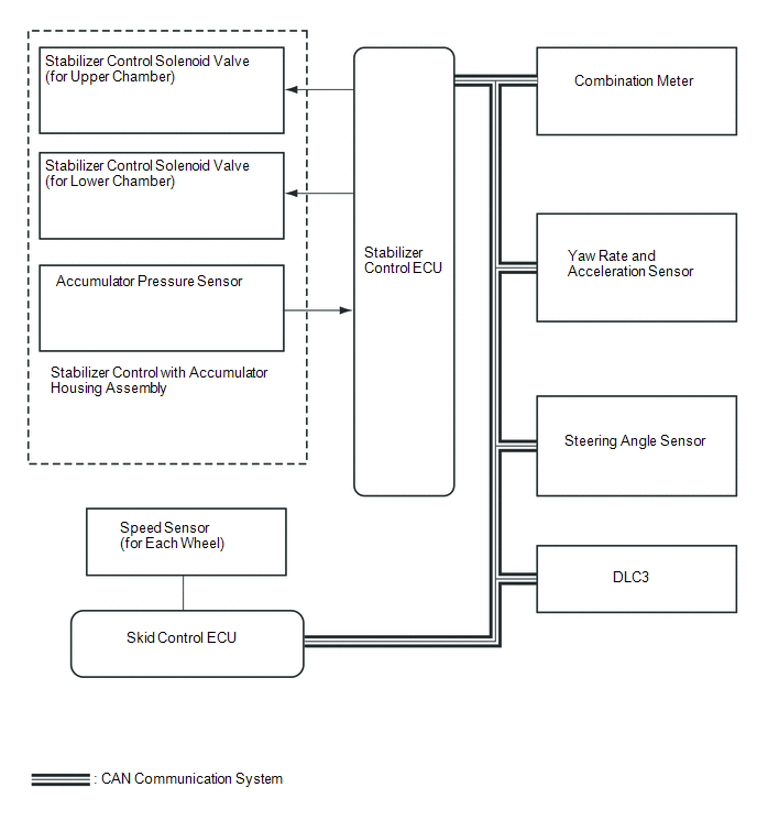 Communication Table
|
Sender |
Receiver |
Signal |
Line |
|---|---|---|---|
|
ECM |
Stabilizer control ECU |
|
CAN communication |
|
Skid control ECU |
Stabilizer control ECU |
|
CAN communication |
|
Yaw rate and acceleration sensor |
Stabilizer control ECU |
|
CAN communication |
|
Steering angle sensor |
Stabilizer control ECU |
|
CAN communication |
|
Stabilizer control ECU |
Combination meter |
KDSS indicator light signal |
CAN communication |
 Parts Location
PARTS LOCATION
ILLUSTRATION
...
 How To Proceed With Troubleshooting
CAUTION / NOTICE / HINT
HINT:
*: Use the Techstream.
PROCEDURE
1.
VEHICLE BROUGHT TO WORKSHOP
NEXT
...
Other materials about Toyota 4Runner:
Jam Protection Function does not Operate
DESCRIPTION
This problem may occur in all door windows.
The jam protection function operates within a specified range during
the manual up or auto up operation.
PROCEDURE
1.
PERFORM INITIALIZATION
(a) ...
Sliding Roof Control Switch Circuit
DESCRIPTION
The sliding roof drive gear sub-assembly (sliding roof ECU) receives sliding
roof switch signals and drives its built-in motor.
WIRING DIAGRAM
CAUTION / NOTICE / HINT
NOTICE:
When the sliding roof drive gear sub-assembly (sliding roof ECU) ...
0.0233