Toyota 4Runner: System Diagram
SYSTEM DIAGRAM
 Communication Table
|
Transmitting ECU |
Receiving ECU |
Signal |
Communication Method |
|---|---|---|---|
|
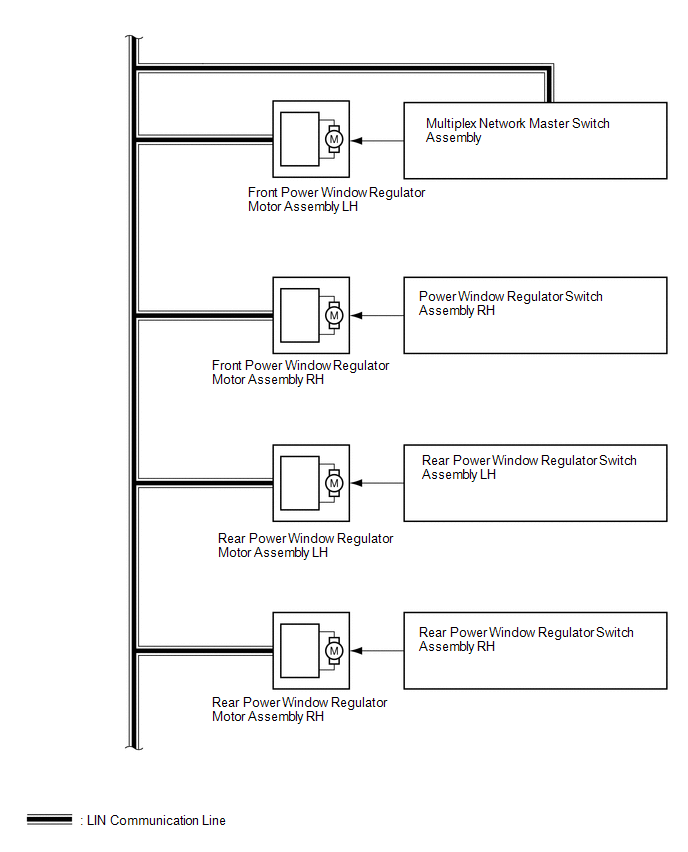
Multiplex network master switch assembly |
|
Power window auto up and down signal |
LIN |
|
Power window remote up and down signal |
LIN |
|
|
Main body ECU (Multiplex network body ECU) |
|
Power window operation permission signal |
LIN |
|
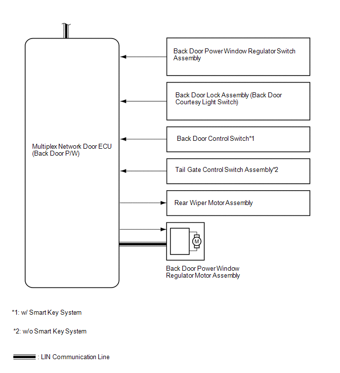
Main body ECU (Multiplex network body ECU) |
Multiplex network door ECU (Back door P/W) |
Back door power window operation permission signal |
LIN |
|
Multiplex network door ECU (Back door P/W) |
Main body ECU (Multiplex network body ECU) |
Power window position signal |
LIN |
|
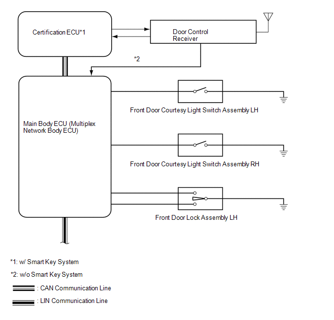
Certification ECU* |
Main body ECU (Multiplex network body ECU) |
Wireless power window up and down signal |
CAN |
- *: w/ Smart Key System
 Parts Location
PARTS LOCATION
ILLUSTRATION
ILLUSTRATION
ILLUSTRATION
...
 System Description
SYSTEM DESCRIPTION
1. POWER WINDOW CONTROL SYSTEM DESCRIPTION
(a) The power window control system controls the power window operation using
the power window regulator motors. The main controls of ...
Other materials about Toyota 4Runner:
Terminals Of Ecu
TERMINALS OF ECU
1. CHECK NO. 1 AIR CONDITIONING AMPLIFIER ASSEMBLY
(a) Disconnect the F42 No. 1 air conditioning amplifier assembly connector.
(b) Measure the voltage and resistance according to the value(s) in the table
below.
Terminal No. ...
Vehicle Speed Signal Circuit between Radio Receiver and Combination Meter
DESCRIPTION
for Automatic Sound Levelizer (ASL):
This circuit is necessary for the Automatic Sound Levelizer (ASL) built
into the radio and display receiver assembly.
The Automatic Sound Levelizer (ASL) function automatically adjusts the
a ...
0.0261