Toyota 4Runner: System Diagram
SYSTEM DIAGRAM
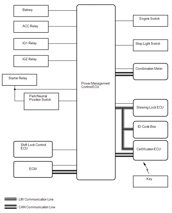 Communication Table
|
Transmitting ECU (Transmitter) |
Receiving ECU (Receiver) |
Signal |
Line |
|---|---|---|---|
|
ECM |
Power management control ECU |
Crankshaft position sensor signal |
CAN/Serial communication |
|
Combination meter |
Power management control ECU |
Vehicle speed signal |
CAN/Serial communication |
|
Steering lock ECU |
Power management control ECU |
Steering lock/unlock signal |
LIN/Serial communication |
|
Certification ECU |
Power management control ECU |
LIN master signal |
LIN |
|
Power management control ECU |
Certification ECU |
ID required signal |
LIN |
|
Key existence condition signal |
CAN |
 System Description
SYSTEM DESCRIPTION
1. PUSH-BUTTON START DESCRIPTION
(a) The push-button start function uses a push-type engine switch, which the
driver can operate by merely carrying the key. This system consists ...
 How To Proceed With Troubleshooting
CAUTION / NOTICE / HINT
HINT:
Use these procedures to troubleshoot the push-button start function.
*: Use the Techstream.
PROCEDURE
1.
VEHICLE BROUGHT T ...
Other materials about Toyota 4Runner:
Rear Airbag Sensor RH Circuit Malfunction (B1630/23,B1635/24)
DESCRIPTION
The rear airbag sensor consists of the safing sensor, diagnostic circuit,
lateral deceleration sensor, etc.
If the center airbag sensor receives signals from the lateral deceleration
sensor, it determines whether the SRS should ...
Installation
INSTALLATION
CAUTION / NOTICE / HINT
HINT:
Use the same procedure for the RH and LH sides.
The procedure listed below is for the LH side.
A bolt without a torque specification is shown in the standard bolt
chart (See page ).
PROC ...
0.0267