Toyota 4Runner: System Diagram
SYSTEM DIAGRAM
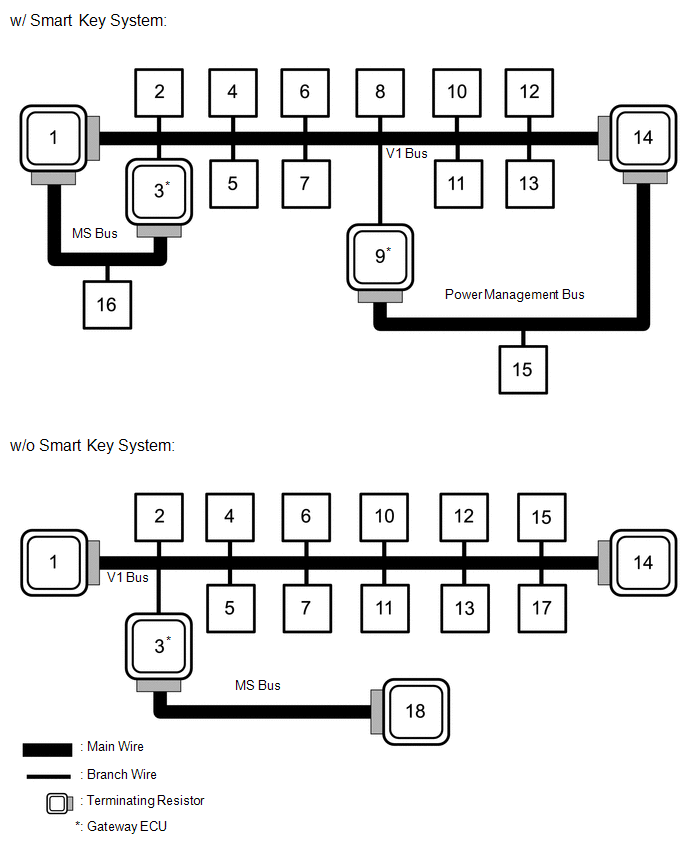 w/ Smart Key System
|
No. |
ECU/Sensor Name |
|---|---|
|
1 |
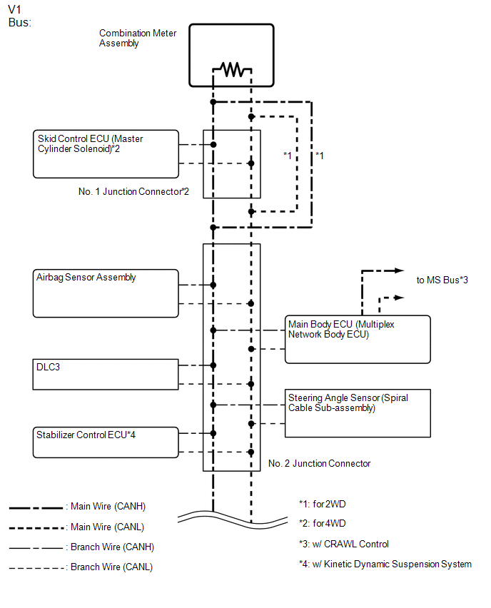
Combination meter assembly |
|
2 |
Skid control ECU (master cylinder solenoid)*1 |
|
3 |
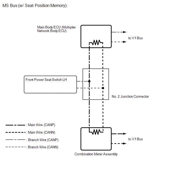
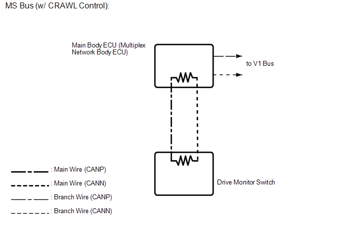
Main body ECU (multiplex network body ECU) |
|
4 |
Airbag sensor assembly |
|
5 |
Steering angle sensor (spiral cable sub-assembly) |
|
6 |
DLC3 |
|
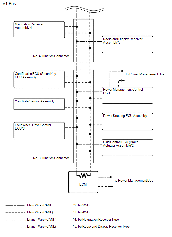
7 |
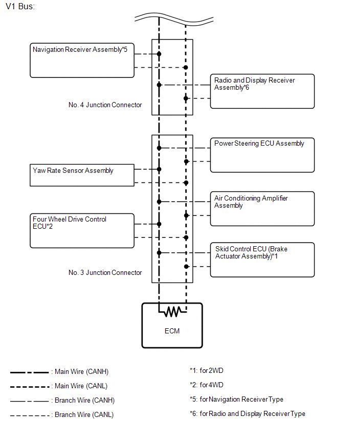
Navigation receiver assembly*2 or radio and display receiver assembly*3 |
|
8 |
Certification ECU (smart key ECU assembly) |
|
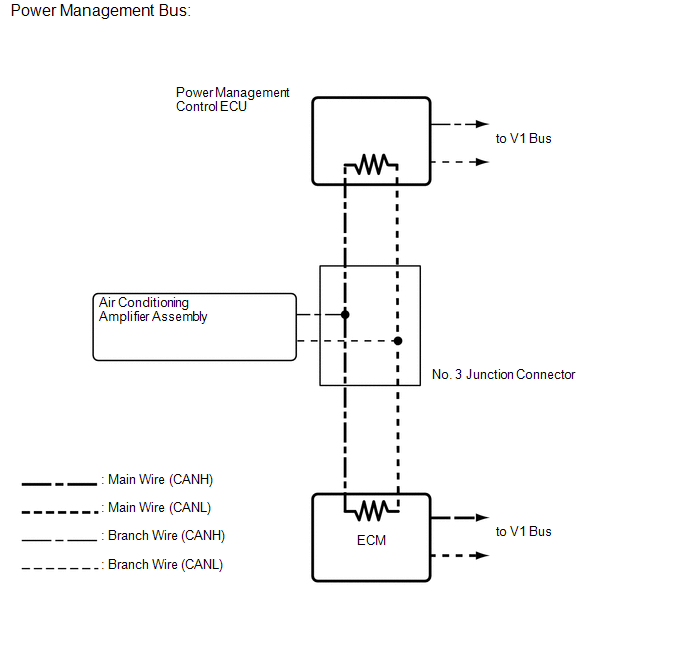
9 |
Power management control ECU |
|
10 |
Yaw rate sensor assembly |
|
11 |
Power steering ECU assembly |
|
12 |
Four wheel drive control ECU*1 |
|
13 |
Skid control ECU (brake actuator assembly)*4 |
|
14 |
ECM |
|
15 |
Air conditioning amplifier assembly |
|
16 |
Front power seat switch LH*5 |
- *1: for 4WD
- *2: for Navigation Receiver Type
- *3: for Radio and Display Receiver Type
- *4: for 2WD
- *5: w/ Seat Position Memory
|
No. |
ECU/Sensor Name |
|---|---|
|
1 |
Combination meter assembly |
|
2 |
Skid control ECU (master cylinder solenoid)*1 |
|
3 |
Main body ECU (multiplex network body ECU) |
|
4 |
Airbag sensor assembly |
|
5 |
Steering angle sensor (spiral cable sub-assembly) |
|
6 |
DLC3 |
|
7 |
Navigation receiver assembly*2 or radio and display receiver assembly*3 |
|
10 |
Yaw rate sensor assembly |
|
11 |
Power steering ECU assembly |
|
12 |
Four wheel drive control ECU*1 |
|
13 |
Skid control ECU (brake actuator assembly)*4 |
|
14 |
ECM |
|
15 |
Air conditioning amplifier assembly |
|
17 |
Stabilizer control ECU*5 |
|
18 |
Drive monitor switch*6 |
- *1: for 4WD
- *2: for Navigation Receiver Type
- *3: for Radio and Display Receiver Type
- *4: for 2WD
- *5: w/ Kinetic Dynamic Suspension System
- *6: w/ CRAWL Control
1. w/ Smart Key System:
2. w/o Smart Key System:
 System Description
SYSTEM DESCRIPTION
1. BRIEF DESCRIPTION
(a) The CAN (Controller Area Network) is a serial data communication system for
real-time application. It is a vehicle multiplex communication system which ...
 How To Proceed With Troubleshooting
CAUTION / NOTICE / HINT
IMPORTANT POINTS CONCERNING TROUBLESHOOTING
CAUTION:
Wait at least 90 seconds after disconnecting the cable from the negative (-)
battery terminal to disable the SRS syste ...
Other materials about Toyota 4Runner:
Removal
REMOVAL
PROCEDURE
1. DISCONNECT CABLE FROM NEGATIVE BATTERY TERMINAL
CAUTION:
Wait at least 90 seconds after disconnecting the cable from the negative (-)
battery terminal to disable the SRS system.
NOTICE:
When disconnecting the cable, some systems ne ...
Installation
INSTALLATION
PROCEDURE
1. INSTALL WINDSHIELD WASHER MOTOR AND PUMP ASSEMBLY
(a) Install the windshield washer motor and pump assembly to the packing of the
washer jar.
2. INSTALL WASHER JAR
(a) Attach the guide to install the washer jar, and ...
0.0078