Toyota 4Runner: Terminals Of Ecu
TERMINALS OF ECU
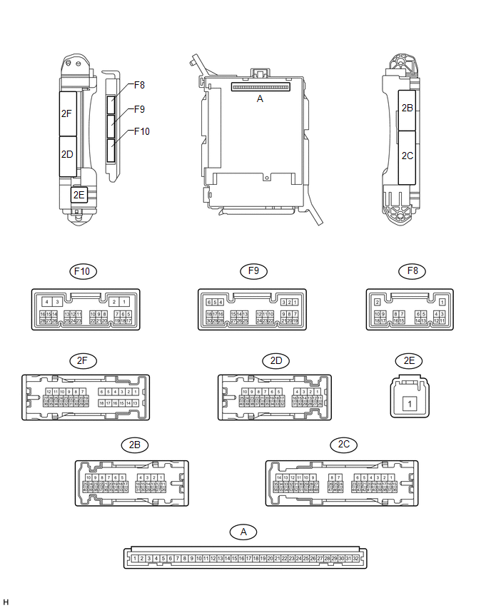
1. CHECK DRIVER SIDE JUNCTION BLOCK ASSEMBLY AND MAIN BODY ECU (MULTIPLEX NETWORK BODY ECU)
(a) Remove the main body ECU (multiplex network body ECU) (See page
.gif) ).
).
(b) Measure the voltage and resistance according to the value(s) in the table below.
|
Terminal No. (Symbol) |
Wiring Color |
Terminal Description |
Condition |
Specified Condition |
|---|---|---|---|---|
|
A-30 (BECU) - Body ground |
- |
Battery power supply |
Always |
11 to 14 V |
|
A-31 (ALTB) - Body ground |
- |
Battery power supply |
Always |
11 to 14 V |
|
A-32 (IG) - Body ground |
- |
Ignition switch power supply |
Ignition switch ON |
11 to 14 V |
|
A-32 (IG) - Body ground |
- |
Ignition switch power supply |
Ignition switch off |
Below 1 V |
|
A-29 (ACC) - Body ground |
- |
ACC power supply |
Ignition switch ACC |
11 to 14 V |
|
A-29 (ACC) - Body ground |
- |
ACC power supply |
Ignition switch off |
Below 1 V |
|
A-11 (GND1) - Body ground |
- |
Ground |
Always |
Below 1 Ω |
|
F10-3 (GND2) - Body ground |
W-B - Body ground |
Ground |
Always |
Below 1 Ω |
|
F9-17 (KSW) - Body ground |
B - Body ground |
Unlock warning switch input |
No key in ignition key cylinder |
10 kΩ or higher |
|
F9-17 (KSW) - Body ground |
B - Body ground |
Unlock warning switch input |
Key inserted in ignition key cylinder |
Below 1 Ω |
If the result is not as specified, there may be a malfunction in the wire harness.
(c) Install the main body ECU (multiplex network body ECU).
(d) Measure the voltage according to the value(s) in the table below.
|
Terminal No. (Symbol) |
Wiring Color |
Terminal Description |
Condition |
Specified Condition |
|---|---|---|---|---|
|
2F-27 (FLCY) - Body ground |
R - Body ground |
Front door LH courtesy switch input |
Front door LH open |
Below 1 V |
|
2F-27 (FLCY) - Body ground |
R - Body ground |
Front door LH courtesy switch input |
Front door LH closed |
11 to 14 V |
If the result is not as specified, the main body ECU (multiplex network body ECU) or driver side junction block assembly may have a malfunction.
 Problem Symptoms Table
PROBLEM SYMPTOMS TABLE
HINT:
Use the table below to help determine the cause of problem symptoms.
If multiple suspected areas are listed, the potential causes of the symptoms
are lis ...
 Data List / Active Test
DATA LIST / ACTIVE TEST
1. READ DATA LIST
HINT:
Using the Techstream to read the Data List allows the values or states of switches,
sensors, actuators and other items to be read without removing ...
Other materials about Toyota 4Runner:
No Sound can be Heard from Speakers
PROCEDURE
1.
CHECK AUDIO SETTINGS
(a) In sound output setting mode, set volume, fader and balance to the initial
values and check that the sound is normal.
OK:
Audio system returns to normal.
HINT:
Sound quality adjustm ...
Rocker Panel Moulding(w/ Intuitive Parking Assist System)
Components
COMPONENTS
ILLUSTRATION
Installation
INSTALLATION
CAUTION / NOTICE / HINT
HINT:
Use the same procedure for both the RH and LH sides.
The procedure listed below is for the LH side.
PROCEDURE
1. INSTALL NO. 6 ROCKER PA ...
0.0085