Toyota 4Runner: Terminals Of Ecu
TERMINALS OF ECU
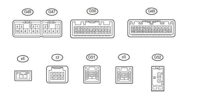
1. RADIO AND DISPLAY RECEIVER ASSEMBLY
|
Terminal No. (Symbols) |
Wiring Color |
Terminal Description |
Condition |
Specification |
|---|---|---|---|---|
|
G48-1 (FR+) - G48-7 (GND) |
P - BR |
Sound signal (Front Right) |
Audio system playing |
A waveform synchronized with sounds is output |
|
G48-2 (FL+) - G48-7 (GND) |
LG - BR |
Sound signal (Front Left) |
Audio system playing |
A waveform synchronized with sounds is output |
|
G48-3 (ACC) - G48-7 (GND) |
GR - BR |
Power source (ACC) |
Ignition switch off |
Below 1 V |
|
Ignition switch ACC |
11 to 14 V |
|||
|
G48-4 (B) - G48-7 (GND) |
SB - BR |
Power source (+B) |
Always |
11 to 14 V |
|
G48-5 (FR-) - G48-7 (GND) |
Y - BR |
Sound signal (Front Right) |
Audio system playing |
A waveform synchronized with sounds is output |
|
G48-6 (FL-) - G48-7 (GND) |
L - BR |
Sound signal (Front Left) |
Audio system playing |
A waveform synchronized with sounds is output |
|
G48-7 (GND) - Body ground |
BR - Body ground |
Ground |
Always |
Below 1 V |
|
G48-10 (ILL+) - G48-7 (GND) |
G - BR |
Illumination signal |
Light control switch off |
Below 1 V |
|
Light control switch in tail or head position |
11 to 14 V |
|||
|
G47-1 (RR+) - G48-7 (GND) |
R - BR |
Sound signal (Rear Right) |
Audio system playing |
A waveform synchronized with sounds is output |
|
G47-2 (RL+) - G48-7 (GND) |
B - BR |
Sound signal (Rear Left) |
Audio system playing |
A waveform synchronized with sounds is output |
|
G47-3 (RR-) - G48-7 (GND) |
W - BR |
Sound signal (Rear Right) |
Audio system playing |
A waveform synchronized with sounds is output |
|
G47-5 (ILL-) - G48-7 (GND) |
W - BR |
Illumination signal |
Ignition switch off |
Below 1 V |
|
Light control switch in tail or head position |
Pulse generation |
|||
|
G47-6 (RL-) - G48-7 (GND) |
Y - BR |
Sound signal (Rear Left) |
Audio system playing |
A waveform synchronized with sounds is output |
|
G49-1 (IG) - G48-7 (GND) |
L - BR |
Power source (IG) |
Ignition switch off |
Below 1 V |
|
Ignition switch ON |
11 to 14 V |
|||
|
G49-2 (REV) - G48-7 (GND) |
R - BR |
Reverse signal |
See "Vehicle Signal Check Mode" in Operation Check (See page
|
- |
|
G49-4 (MACC) - G48-7 (GND) |
R - BR |
Microphone power supply |
Ignition switch off |
Below 1 V |
|
Ignition switch ACC |
4 to 6 V |
|||
|
G49-5 (MIN+) - G48-7 (GND) |
B - BR |
Microphone voice signal |
See "Check Microphone" in Operation Check (See page
|
- |
|
G49-6 (SNS2) - G48-7 (GND) |
G - BR |
Microphone connection detection signal |
Always |
Below 1 V |
|
G49-9 (CANH) |
P |
CAN communication signal |
- |
- |
|
G49-10 (CANL) |
W |
CAN communication signal |
- |
- |
|
G49-11 (AGND) - Body ground |
Shield - Body ground |
Shield ground |
Always |
Below 1 V |
|
G49-12 (SG) - G48-7 (GND) |
Shield - BR |
External device connection detection signal |
Always |
Below 1 V |
|
G49-15 (PKB) - G48-7 (GND) |
LG - BR |
Parking Bake signal |
See "Vehicle Signal Check Mode" in Operation Check (See page
|
- |
|
G49-17 (SPD) - G48-7 (GND) |
SB - BR |
Vehicle speed signal |
See "Vehicle Signal Check Mode" in Operation Check (See page
|
- |
|
G49-18 (SGND) - Body ground |
Shield - Body ground |
Shield ground |
Always |
Below 1 V |
|
G49-19 (MIN-) - G48-7 (GND) |
W - BR |
Microphone voice signal |
See "Check Microphone" in Operation Check (See page
|
- |
|
G49-21 (SW1) - G49-23 (SWG) |
W - L |
Steering pad switch signal |
No switch pushed |
2.97 to 3.56 V |
|
Up switch pushed |
0.27 to 0.35 V |
|||
|
Down switch pushed |
0.86 to 1.03 V |
|||
|
Volume+ switch pushed |
1.51 to 1.79 V |
|||
|
Volume- switch pushed |
2.22 to 2.66 V |
|||
|
G49-22 (SW2) - G49-23 (SWG) |
R - L |
Steering pad switch signal |
No switch pushed |
2.97 to 3.56 V |
|
MODE/HOLD switch pushed |
0.27 to 0.35 V |
|||
|
On hook switch pushed |
0.86 to 1.03 V |
|||
|
Off hook switch pushed |
1.51 to 1.79 V |
|||
|
Voice switch pushed |
2.22 to 2.66 V |
|||
|
G49-23 (SWG) - Body ground |
L - Body ground |
Steering pad switch ground |
Always |
Below 1 V |
|
G49-24 (SW3) - G49-23 (SWG) |
P - L |
Steering pad switch signal |
No switch pushed |
2.97 to 3.56 V |
|
Enter switch pushed |
0.27 to 0.35 V |
|||
|
Back switch pushed |
0.86 to 1.03 V |
|||
|
Right switch pushed |
1.51 to 1.79 V |
|||
|
Left switch pushed |
2.22 to 2.66 V |
|||
|
G49-25 (ADPG) - G48-7 (GND) |
V - BR |
External device connection detection signal |
External device connected |
Below 1 V |
|
External device not connected |
2.1 to 3 V |
|||
|
G49-26 (VAR+) - G49-27 (VA-) |
R - W |
Sound signal (Right) |
External device playing (When stereo jack used) |
A waveform synchronized with sounds is output |
|
G49-27 (VA-) - G48-7 (GND) |
W - BR |
Ground |
Always |
Below 1 V |
|
G49-28 (VAL+) - G49-27 (VA-) |
B - W |
Sound signal (Left) |
External device playing (When stereo jack used) |
A waveform synchronized with sounds is output |
|
G50-11 (CA+) - G48-7 (GND) |
R - BR |
Television camera power supply |
Ignition switch ON Shift lever in R |
5.5 to 7.05 V |
|
G50-12 (V+) - G48-7 (GND) |
W - BR |
Video signal |
Ignition switch ON Shift lever in R Camera lens not covered, displaying an image |
Pulse generation (Refer to waveform 1) |
|
Ignition switch ON Shift lever in R Camera lens covered, blacking out screen |
Pulse generation (Refer to waveform 2) |
|||
|
G50-23 (CGND) - Body ground |
Shield - Body ground |
Shield ground |
Always |
Below 1 V |
|
G50-24 (V-) - G48-7 (GND) |
B - BR |
Ground |
Always |
Below 1 V |
|
G51-1 (USV1) |
# |
Power source |
- |
- |
|
G51-2 (US1-) |
# |
Data signal |
- |
- |
|
G51-3 (US1+) |
# |
Data signal |
- |
- |
|
G51-4 (UGD1) |
# |
Ground |
- |
- |
|
G51-5 (USG1) |
# |
Shield ground |
- |
- |
|
G52-1 (FMSUB1) |
# |
Radio SUB signal |
- |
- |
|
G52-2 (R+B1) - G48-7 (GND) |
# - BR |
Power source of antenna |
Ignition switch ACC Radio switch on and FM or AM selected |
11 to 14 V |
|
G52-3 (AMFM1) |
# |
Radio MAIN signal |
- |
- |
|
s5-1 (USV4)*1 |
# |
Power source |
- |
- |
|
s5-2 (US4-)*1 |
# |
Data signal |
- |
- |
|
s5-3 (US4+)*1 |
# |
Data signal |
- |
- |
|
s5-4 (UGD4)*1 |
# |
Ground |
- |
- |
|
s6-1 (LV1)*1 |
B |
LVDS communication signal |
- |
- |
|
t3-3 (ACC2) - G48-7 (GND)*1 |
Y - BR |
Power source (ACC) |
Ignition switch off |
Below 1 V |
|
Ignition switch ACC |
11 to 14V |
|||
|
t3-4 (+B2) - G48-7 (GND)*1 |
R - BR |
Power source (+B) |
Always |
11 to 14V |
|
t3-8 (GND2) - Body ground*1 |
B - Body ground |
Ground |
Always |
Below 1 V |
.gif) )
)#: There is no wire color information.
*1: w/ SDARS System
(a) Reference (Oscilloscope waveform):
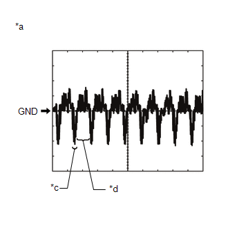
(1) Waveform 1 (camera lens not covered, displaying an image)
|
Item |
Content |
|---|---|
|
Measurement terminal |
G50-12 (V+) - G48-7 (GND) |
|
Measurement setting |
200 mV/DIV., 50 μsec./DIV. |
|
Condition |
Ignition switch ON, Shift lever in R |
HINT:
The video waveform changes according to the image sent by the television camera assembly.
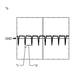
(2) Waveform 2 (camera lens covered, blacking out the screen)
|
Item |
Content |
|---|---|
|
Measurement terminal |
G50-12 (V+) - G48-7 (GND) |
|
Measurement setting |
200 mV/DIV., 50 μsec./DIV. |
|
Condition |
Ignition switch ON, Shift lever in R |
HINT:
The video waveform changes according to the image sent by the rear television camera assembly.
Text in Illustration|
*a |
Waveform 1 (camera lens not covered, displaying an image) |
|
*b |
Waveform 2 (camera lens covered, blacking out the screen) |
|
*c |
Synchronization Signal |
|
*d |
Video Waveform |
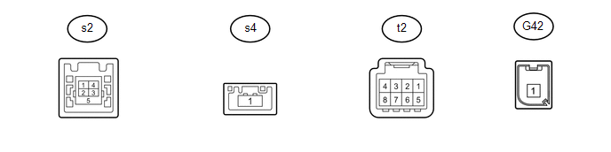
2. STEREO COMPONENT TUNER ASSEMBLY (w/ SDARS System)
|
Terminal No. (Symbol) |
Wiring Color |
Terminal Description |
Condition |
Specified Condition |
|---|---|---|---|---|
|
t2-3 (ACC2) - t2-8 (GND2) |
Y - B |
Power source (ACC) |
Ignition switch off |
Below 1 V |
|
Ignition switch ACC |
11 to 14 V |
|||
|
t2-4 (+B2) - t2-8 (GND2) |
R - B |
Power source (+B) |
Always |
11 to 14 V |
|
t2-8 (GND2) - Body ground |
B - Body ground |
Ground |
Always |
Below 1 V |
|
s2-1 (USV4) |
# |
Power source |
- |
- |
|
s2-2 (USV4-) |
# |
Data signal |
- |
- |
|
s2-3 (USV4+) |
# |
Data signal |
- |
- |
|
s2-4 (UGD4) |
# |
Ground |
- |
- |
|
s2-5 (USG4) |
# |
Shield ground |
- |
- |
|
s4-1 (LV1) |
# |
LVDS communication signal |
- |
- |
|
G42-1 (SDARS1) |
# |
Satellite radio signal |
- |
- |
- #: There is no wire color information.
 Problem Symptoms Table
PROBLEM SYMPTOMS TABLE
NOTICE:
After replacing the stereo component tuner assembly of vehicles subscribed to
pay-type satellite radio broadcasts, XM radio ID registration is necessary (w/ SDARS
...
 Dtc Check / Clear
DTC CHECK / CLEAR
1. CHECK DTC (CHECK USING TECHSTREAM)
(a) Connect the Techstream to the DLC3.
(b) Turn the ignition switch to ON.
(c) Turn the Techstream on.
(d) Enter the following menus: Body ...
Other materials about Toyota 4Runner:
Seat Heater Control
Components
COMPONENTS
ILLUSTRATION
Removal
REMOVAL
CAUTION / NOTICE / HINT
CAUTION:
Wear protective gloves. Sharp areas on the parts may injure your hands.
HINT:
Use the same procedure for the RH and LH sides.
The procedure listed be ...
Installation with LATCH system (rear/second row seats only)
Installing on the rear seats (vehicles without third row seats)
Fold the seatback while pulling the seatback angle adjustment lever. Return
the seatback and secure it at the first lock position.
Type A
Latch the hooks of the lower straps onto the LATC ...
0.0284