Toyota 4Runner: Terminals Of Ecu
TERMINALS OF ECU
1. CHECK CLEARANCE WARNING ECU

(a) Disconnect the F95 clearance warning ECU assembly connector.
(b) Measure the voltage and resistance according to the value(s) in the table below.
|
Terminal No. (Symbol) |
Wiring Color |
Terminal Description |
Condition |
Specified Condition |
|---|---|---|---|---|
|
F95-1 (IG) - F95-22 (E) |
L - W-B |
Back sonar or clearance sonar switch assembly power source signal |
Ignition switch ON, back sonar or clearance sonar switch assembly on |
11 to 14 V |
|
Ignition switch ON, back sonar or clearance sonar switch assembly off |
Below 1 V |
|||
|
F95-22 (E) - Body ground |
W-B - Body ground |
Ground |
Always |
Below 1 Ω |
(c) Reconnect the F95 clearance warning ECU assembly connector.
(d) Measure the voltage and check for pulses according to the value(s) in the table below.
|
Terminal No. (Symbol) |
Wiring Color |
Terminal Description |
Condition |
Specified Condition |
|---|---|---|---|---|
|
F95-5 (SPD) - F95-22 (E) |
SB - W-B |
Vehicle speed signal |
Ignition switch ON, back sonar or clearance sonar switch on |
Alternating between 1.5 to 4.5 V |
|
F95-7 (PL) - F95-22 (E) |
L - W-B |
Shift position signal |
Ignition switch ON, shift lever in P |
11 to 14 V |
|
Ignition switch ON, shift lever not in P |
Below 1 V |
|||
|
F95-9 (L4) - F95-22 (E) |
B - W-B |
Front ultrasonic sensor indicator signal (Front right sensor) |
Clearance warning indicator for front right sensor illuminates |
Below 3 V |
|
F95-12 (E6) - F95-22 (E) |
W - W-B |
Front ultrasonic sensor ground (Front left sensor) |
Always |
Below 1 Ω |
|
F95-13 (S6) - F95-22 (E) |
B - W-B |
Front ultrasonic sensor indicator signal (Front left sensor) |
Ignition switch ON, back sonar or clearance sonar switch on, sensor detects obstacle |
Pulse generation (See waveform 1) |
|
F95-15 (E4) - F95-22 (E) |
LG - W-B |
Rear ultrasonic sensor ground (Rear center left sensor) |
Always |
Below 1 Ω |
|
F95-16 (S4) - F95-22 (E) |
L - W-B |
Rear ultrasonic sensor indicator signal (Rear center left sensor) |
Ignition switch ON, back sonar or clearance sonar switch on, shift lever in R |
Pulse generation (See waveform 1) |
|
F95-17 (E1) - F95-22 (E) |
R - W-B |
Rear ultrasonic sensor ground (Rear right sensor) |
Always |
Below 1 Ω |
|
F95-18 (S1) - F95-22 (E) |
W - W-B |
Rear ultrasonic sensor indicator signal (Rear right sensor) |
Ignition switch ON, back sonar or clearance sonar switch on, shift lever in R |
Pulse generation (See waveform 1) |
|
F95-19 (CBZ) - F95-22 (E) |
L - W-B |
No. 1 clearance warning buzzer signal |
Buzzer not sounding |
Below 1 V |
|
Sonar detecting obstacle (Buzzer sounding) |
11 to 14 V |
|||
|
F95-20 (FF) - F95-22 (E) |
P - W-B |
Clearance warning buzzer signal |
Buzzer sounding |
Pulse generation (See waveform 1) |
|
F95-23 (RL) - F95-22 (E) |
R - W-B |
Shift position signal |
Ignition switch ON, shift lever in R |
11 to 14 V |
|
Ignition switch ON, shift lever not in R |
Below 1 V |
|||
|
F95-24 (TL) - F95-22 (E) |
G - W-B |
Illumination signal |
Ignition switch ON, light control switch on |
11 to 14 V |
|
Ignition switch ON, light control switch off |
Below 1 V |
|||
|
F95-26 (L5) - F95-22 (E) |
P - W-B |
Ultrasonic sensor (front left sensor) indicator signal |
Clearance warning indicator for front left sensor illuminates |
Below 3 V |
|
F95-28 (L1) - F95-22 (E) |
Y - W-B |
Ultrasonic sensor (rear right sensor) indicator signal |
Clearance warning indicator for rear right sensor illuminates |
Below 3 V |
|
F95-29 (L2) - F95-22 (E) |
GR - W-B |
Ultrasonic sensor (rear left sensor) indicator signal |
Clearance warning indicator for rear left sensor illuminates |
Below 3 V |
|
F95-30 (L3) - F95-22 (E) |
SB - W-B |
Ultrasonic sensor (rear center right and left sensor) indicator signal |
Clearance warning indicator for back sensor illuminates |
Below 3 V |
|
F95-31 (L10) - F95-22 (E) |
LG - W-B |
Clearance warning ECU assembly signal |
Clearance warning indicator's operation indicator illuminates |
Below 3 V |
|
F95-33 (E5) - F95-22 (E) |
G - W-B |
Front ultrasonic sensor ground (Front right sensor) |
Always |
Below 1 Ω |
|
F95-34 (S5) - F95-22 (E) |
L - W-B |
Front ultrasonic sensor indicator signal (Front right sensor) |
Ignition switch ON, back sonar or clearance sonar switch on, sensor detects obstacle |
Pulse generation (See waveform 1) |
|
F95-37 (E2) - F95-22 (E) |
R - W-B |
Rear ultrasonic sensor ground (Rear left sensor) |
Always |
Below 1 Ω |
|
F95-38 (S2) - F95-22 (E) |
G - W-B |
Rear ultrasonic sensor communication signal (Rear left sensor) |
Ignition switch ON, back sonar or clearance sonar switch on, shift lever in R |
Pulse generation (See waveform 1) |
|
F95-39 (E3) - F95-22 (E) |
Y - W-B |
Rear ultrasonic sensor ground (Rear center right sensor) |
Always |
Below 1 Ω |
|
F95-40 (S3) - F95-22 (E) |
B - W-B |
Rear ultrasonic sensor communication signal (Rear center right sensor) |
Ignition switch ON, back sonar or clearance sonar switch on, shift lever in R |
Pulse generation (See waveform 1) |
(e) Using an oscilloscope, check waveform 1.
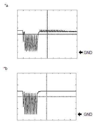 Measurement Condition
|
Item |
Content |
|---|---|
|
Terminal No. (Symbol) |
F95-12 (E6) - F95-13 (S6) F95-15 (E4) - F95-16 (S4) F95-17 (E1) - F95-18 (S1) F95-33 (E5) - F95-34 (S5) F95-37 (E2) - F95-38 (S2) F95-39 (E3) - F95-40 (S3) |
|
Tool Setting |
2 V/DIV., 0.1 msec./DIV. |
|
Condition |
Ignition switch ON, back sonar or clearance sonar switch on, shift lever in R |
|
*a |
Ultrasonic sensor is normal |
|
*b |
Open circuit in ultrasonic sensor |
 Problem Symptoms Table
PROBLEM SYMPTOMS TABLE
HINT:
Use the table below to help determine the cause of problem symptoms. If multiple
suspected areas are listed, the potential causes of the symptoms are listed in order
...
 Park / Neutral Position Switch Circuit
DESCRIPTION
This circuit sends the park/neutral position switch assembly signals to the clearance
warning ECU assembly.
WIRING DIAGRAM
CAUTION / NOTICE / HINT
NOTICE:
Inspect the fuses for ci ...
Other materials about Toyota 4Runner:
Rear Airbag Sensor Assembly RH Initialization Incomplete (B1633/81,B1638/82)
DESCRIPTION
The circuit for the side collision sensor LH or RH (to determine deployment of
the front seat side airbag LH or RH and curtain shield airbag LH or RH) is composed
of the center airbag sensor, side airbag sensor LH or RH and rear airbag sensor ...
Torque Converter Clutch Pressure Control Solenoid Control Circuit Electrical
(Shift Solenoid Valve SLU) (P2759)
DESCRIPTION
The amount of current flow to the solenoid is controlled by the duty ratio* of
the ECM output signal. During the lock-up operation, if the duty ratio increases,
the lock-up hydraulic pressure increases.
HINT:
*: The duty ratio is the ratio ...
0.0265