Toyota 4Runner: Transfer Indicator Switch
Components
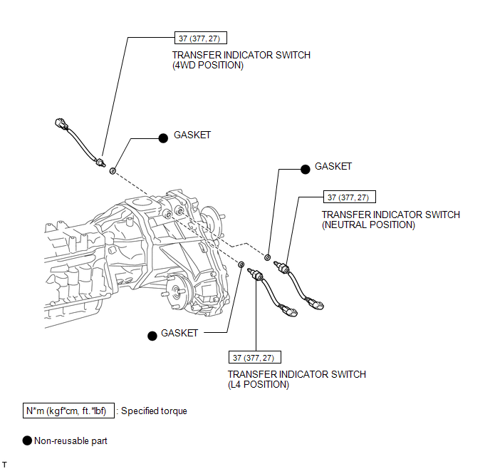
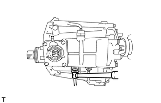
COMPONENTS
ILLUSTRATION
Inspection
INSPECTION
PROCEDURE
1. INSPECT TRANSFER INDICATOR SWITCH (4WD POSITION)
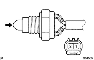
(a) Measure the resistance according to the value(s) in the table below.
Standard Resistance:
|
Tester Connection |
Switch Condition |
Specified Condition |
|---|---|---|
|
1 - 2 |
Pushed |
Below 1 Ω |
|
1 - 2 |
Not pushed |
100 kΩ or higher |
If the resistance is not as specified, replace the switch.
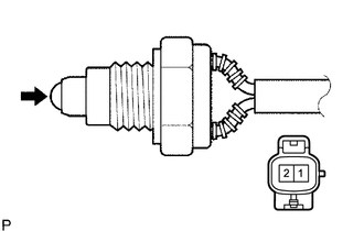
2. INSPECT TRANSFER INDICATOR SWITCH (L4 POSITION)
(a) Measure the resistance according to the value(s) in the table below.
Standard Resistance:
|
Tester Connection |
Switch Condition |
Specified Condition |
|---|---|---|
|
1 - 2 |
Pushed |
Below 1 Ω |
|
1 - 2 |
Not pushed |
100 kΩ or higher |
If the resistance is not as specified, replace the switch.
3. INSPECT TRANSFER INDICATOR SWITCH (NEUTRAL POSITION)
(a) Measure the resistance according to the value(s) in the table below.
Standard Resistance:
|
Tester Connection |
Switch Condition |
Specified Condition |
|---|---|---|
|
1 - 2 |
Pushed |
Below 1 Ω |
|
1 - 2 |
Not pushed |
100 kΩ or higher |
If the resistance is not as specified, replace the switch.
Removal
REMOVAL
PROCEDURE
1. REMOVE AUTOMATIC TRANSMISSION WITH TRANSFER
(a) Remove the automatic transmission (See page
.gif) ).
).
2. REMOVE TRANSFER INDICATOR SWITCH (4WD POSITION)
|
(a) Using SST, remove the indicator switch and gasket. SST: 09817-16011 |
|
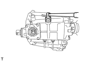
3. REMOVE TRANSFER INDICATOR SWITCH (L4 POSITION)
(a) Using SST, remove the indicator switch and gasket.
SST: 09817-16011
4. REMOVE TRANSFER INDICATOR SWITCH (NEUTRAL POSITION)
(a) Using SST, remove the indicator switch and gasket.
SST: 09817-16011
Installation
INSTALLATION
PROCEDURE
1. INSTALL TRANSFER INDICATOR SWITCH (4WD POSITION)
(a) Using SST, install a new gasket and the indicator switch.
SST: 09817-16011
Torque:
37 N·m {377 kgf·cm, 27 ft·lbf}
2. INSTALL TRANSFER INDICATOR SWITCH (L4 POSITION)
(a) Using SST, install a new gasket and the indicator switch.
SST: 09817-16011
Torque:
37 N·m {377 kgf·cm, 27 ft·lbf}
3. INSTALL TRANSFER INDICATOR SWITCH (NEUTRAL POSITION)
(a) Using SST, install a new gasket and the indicator switch.
SST: 09817-16011
Torque:
37 N·m {377 kgf·cm, 27 ft·lbf}
4. INSTALL AUTOMATIC TRANSMISSION WITH TRANSFER
(a) Install the automatic transmission (See page
.gif) ).
).
 Transfer Case Rear Oil Seal
Components
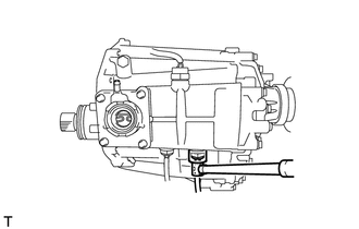
COMPONENTS
ILLUSTRATION
Replacement
REPLACEMENT
PROCEDURE
1. DRAIN TRANSFER OIL
2. REMOVE REAR PROPELLER SHAFT ASSEMBLY
(a) Remove the rear propeller shaft (See page
).
...
 Transfer Oil
On-vehicle Inspection
ON-VEHICLE INSPECTION
PROCEDURE
1. CHECK TRANSFER OIL
(a) Remove the filler plug and gasket.
(b) Check that ...
Other materials about Toyota 4Runner:
Front Differential Carrier Oil Seal(for 4wd)
Components
COMPONENTS
ILLUSTRATION
Replacement
REPLACEMENT
PROCEDURE
1. REMOVE FRONT DIFFERENTIAL CARRIER ASSEMBLY
(a) Remove the front differential carrier assembly (See page
).
2. REMOVE FRONT DRIVE PINION COMPANION FLANGE NUT
(a) Using SS ...
Parts Location
PARTS LOCATION
ILLUSTRATION
ILLUSTRATION
ILLUSTRATION
ILLUSTRATION
ILLUSTRATION
...
0.0072