Toyota 4Runner: Accessory Meter
Components
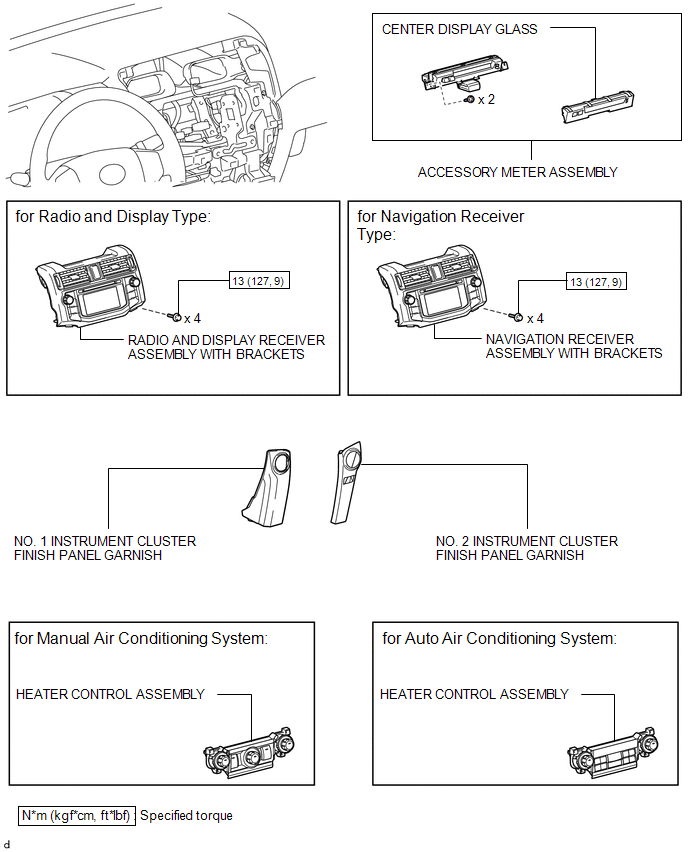
COMPONENTS
ILLUSTRATION
Removal
REMOVAL
PROCEDURE
1. DISCONNECT CABLE FROM NEGATIVE BATTERY TERMINAL
CAUTION:
Wait at least 90 seconds after disconnecting the cable from the negative (-) battery terminal to disable the SRS system.
NOTICE:
When disconnecting the cable, some systems need to be initialized after the cable
is reconnected (See page .gif) ).
).
2. REMOVE NO. 1 INSTRUMENT CLUSTER FINISH PANEL GARNISH
3. REMOVE NO. 2 INSTRUMENT CLUSTER FINISH PANEL GARNISH
4. REMOVE HEATER CONTROL ASSEMBLY
5. REMOVE RADIO AND DISPLAY RECEIVER ASSEMBLY WITH BRACKETS (for Radio and Display Type)
6. REMOVE NAVIGATION RECEIVER ASSEMBLY WITH BRACKETS (for Navigation Receiver Type)
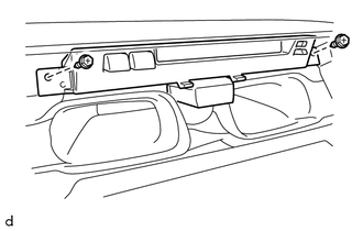
7. REMOVE ACCESSORY METER ASSEMBLY
|
(a) Remove the 2 screws. |
|
|
(b) Disconnect the connector to remove the accessory meter assembly as shown in the illustration. |
|
Disassembly
DISASSEMBLY
PROCEDURE
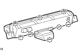
1. REMOVE CENTER DISPLAY GLASS
|
(a) Detach the 8 claws and remove the display glass. |
|
Reassembly
REASSEMBLY
PROCEDURE
1. INSTALL CENTER DISPLAY GLASS
(a) Attach the 8 claws to install the display glass.
Installation
INSTALLATION
PROCEDURE
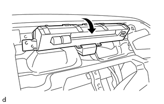
1. INSTALL ACCESSORY METER ASSEMBLY
(a) Connect the connector.
(b) Install the accessory meter assembly with the 2 screws.
2. INSTALL NAVIGATION RECEIVER ASSEMBLY WITH BRACKETS (for Navigation Receiver Type)
.gif)
3. INSTALL RADIO AND DISPLAY RECEIVER ASSEMBLY WITH BRACKETS (for Radio and Display Type)
4. INSTALL HEATER CONTROL ASSEMBLY
5. INSTALL NO. 2 INSTRUMENT CLUSTER FINISH PANEL GARNISH
6. INSTALL NO. 1 INSTRUMENT CLUSTER FINISH PANEL GARNISH
7. CONNECT CABLE TO NEGATIVE BATTERY TERMINAL
NOTICE:
When disconnecting the cable, some systems need to be initialized after the cable
is reconnected (See page ).

 Clock System
...
Other materials about Toyota 4Runner:
Transponder Chip Malfunction (B2793-B2795)
DESCRIPTION
DTC B2793 is stored when a malfunction is found in the key during key
code registration or a key code is not registered normally. Replace the
key if key code registration cannot be performed normally and this DTC is
output.
...
Power Supply Drive Circuit (C1257)
DESCRIPTION
The motor relay (semiconductor relay) is built into the master cylinder solenoid
and drives the pump motor based on a signal from the skid control ECU.
DTC Code
DTC Detection Condition
Trouble Area
...

0.0203