Toyota 4Runner: Accumulator Solenoid Malfunction / Upside (C1831/31,C1832/32)
DESCRIPTION
The stabilizer control ECU receives information from the steering angle sensor, skid control ECU (speed signal) and yaw rate and acceleration sensor via CAN communication. Based on this information, the stabilizer control ECU turns the stabilizer control solenoid valve (built into the stabilizer control with accumulator housing assembly) on or off.
|
DTC Code |
DTC Detection Condition |
Trouble Area |
|---|---|---|
|
C1831/31 C1832/32 |
Either condition is met:
|
|
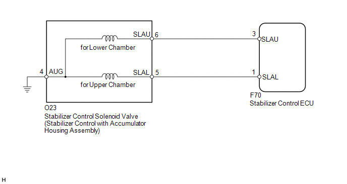
WIRING DIAGRAM

PROCEDURE
|
1. |
READ VALUE USING TECHSTREAM (ACCUMULATOR VALVE) |
(a) Turn the ignition switch off.
(b) Connect the Techstream to the DLC3.
(c) Turn the ignition switch to ON.
(d) Turn the Techstream on.
(e) Enter the following menus: Chassis / KDSS / Data List.
(f) Select the item below in the Data List, and read the value displayed on the Techstream.
KDSS|
Tester Display |
Measurement Item/Range |
Normal Condition |
Diagnostic Note |
|---|---|---|---|
|
Accumulator Valve (Downside) |
Stabilizer control solenoid valve (for Lower Chamber)/ ON or OFF |
ON: Stabilizer control solenoid valve closed OFF: Stabilizer control solenoid valve open |
- |
|
Accumulator Valve (Upside) |
Stabilizer control solenoid valve (for Upper Chamber)/ ON or OFF |
ON: Stabilizer control solenoid valve open OFF: Stabilizer control solenoid valve closed |
- |
(g) Perform the Active Test of the stabilizer control ECU using the Techstream.
KDSS|
Tester Display |
Test Part |
Control Range |
Diagnostic Note |
|---|---|---|---|
|
Accumulator Valve (Upside) |
Stabilizer control solenoid valve (for Upper Chamber) |
Valve ON / OFF |
The operating sound of the solenoid (clicking sound) can be heard. ON: Data List ON OFF: Data List OFF When the Active Test is performed, the solenoid turns on for 3 seconds. |
|
Accumulator Valve (Downside) |
Stabilizer control solenoid valve (for Lower Chamber) |
Valve ON / OFF |
The operating sound of the solenoid (clicking sound) can be heard. ON: Data List ON OFF: Data List OFF When the Active Test is performed, the solenoid turns on for 3 seconds. |
(h) Check that the solenoid operating sound can be heard, and that the Data List display changes between ON and OFF in response to the Active Test.
OK:
Solenoid operating sound can be heard and display changes between ON and OFF in response to Active Test.
| NG | .gif) |
GO TO STEP 3 |
|
|
2. |
RECONFIRM DTC |
(a) Clear the DTCs (See page .gif) ).
).
(b) Check for DTCs (See page .gif) ).
).
Result
|
Result |
Proceed to |
|---|---|
|
DTC is output |
A |
|
DTC is not output |
B |
| A | .gif) |
REPLACE STABILIZER CONTROL ECU |
| B | .gif) |
USE SIMULATION METHOD TO CHECK |
|
3. |
CHECK HARNESS AND CONNECTOR (STABILIZER CONTROL ECU - STABILIZER CONTROL SOLENOID VALVE) |
(a) Disconnect the stabilizer control ECU connector.
(b) Disconnect the stabilizer control with accumulator housing assembly connector.
(c) Measure the resistance according to the value(s) in the table below.
Standard Resistance:
|
Tester Connection |
Condition |
Specified Condition |
|---|---|---|
|
F70-3 (SLAU) - O23-6 (SLAU) |
Always |
Below 1 Ω |
|
F70-3 (SLAU) - Body ground |
Always |
10 kΩ or higher |
|
F70-1 (SLAL) - O23-5 (SLAL) |
Always |
Below 1 Ω |
|
F70-1 (SLAL) - Body ground |
Always |
10 kΩ or higher |
|
O23-4 (AUG) - Body ground |
Always |
Below 1 Ω |
| NG | .gif) |
REPAIR OR REPLACE HARNESS OR CONNECTOR |
|
|
4. |
INSPECT STABILIZER CONTROL SOLENOID VALVE |
(a) Disconnect the stabilizer control with accumulator housing assembly connector.
|
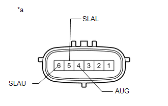
(b) Measure the resistance according to the value(s) in the table below. Standard Resistance: for DTC C1831/31 (for Upper Chamber)
|
|
(c) Check for an operating sound of the stabilizer control solenoid valve.
|
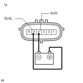
(1) for DTC C1831/31 (for Upper Chamber): Connect terminal 5 (SLAL) to the positive (+) battery terminal, and terminal 4 (AUG) to the negative (-) battery terminal. OK: An operating sound (click sound) can be heard. Text in Illustration
|
|
|
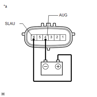
(2) for DTC C1832/32 (for Lower Chamber): Connect terminal 6 (SLAU) to the positive (+) battery terminal, and terminal 4 (AUG) to the negative (-) battery terminal. OK: An operating sound (click sound) can be heard. Text in Illustration
|
|
| OK | .gif) |
REPLACE STABILIZER CONTROL ECU |
| NG | .gif) |
REPLACE STABILIZER CONTROL WITH ACCUMULATOR HOUSING ASSEMBLY |
 Pressure Sensor Malfunction / Upside (C1812/12)
DESCRIPTION
In the KDSS hydraulic circuit, the fluid is contained under pressure. If the
fluid temperature is 20°C (68°F), the pressure is approximately 3.0 MPa (30.6 kgf/cm2,
435 psi).
...
 Steering Angle Sensor Circuit Malfunction (C1884/84)
DESCRIPTION
The stabilizer control ECU receives steering angle information from the steering
angle sensor via CAN communication.
DTC Code
DTC Detection Condition
T ...
Other materials about Toyota 4Runner:
Installation
INSTALLATION
CAUTION / NOTICE / HINT
HINT:
Use the same procedure for the RH and LH sides.
The procedure listed below is for the LH side.
PROCEDURE
1. INSTALL REAR AXLE SHAFT OIL SEAL LH
(a) Using SST and a hammer, install a ...
Adjustment
ADJUSTMENT
CAUTION / NOTICE / HINT
HINT:
Centering bolts are used to mount the hood hinge and hood lock. The
hood and hood lock cannot be adjusted with the centering bolts installed.
Substitute the centering bolts with standard bolts when ...
0.0246

.gif)


