Toyota 4Runner: Adjustment
ADJUSTMENT
PROCEDURE
1. STEERING OFF CENTER ADJUSTMENT PROCEDURE
HINT:
This is the adjustment procedure for when the steering is off center.
(a) Check if the steering wheel is off center.
|
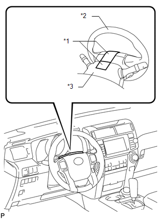
(1) Apply masking tape to the top center of the steering wheel and steering column upper cover. Text in Illustration
|
|
(2) Drive the vehicle in a straight line for 100 m (328 ft.) at a constant speed of 56 km/h (35 mph) and hold the steering wheel to maintain course.
|
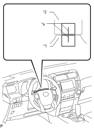
(3) Draw a line on the masking tape as shown in the illustration. Text in Illustration
|
|
(4) Turn the steering wheel to the center position.
HINT:
Look at the upper surface of the steering wheel, steering spoke and SRS airbag line to find the center position.
|
(5) Draw a new line on the masking tape on the steering wheel as shown in the illustration. Text in Illustration
|
|
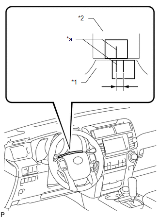
(6) Measure the distance between the 2 lines on the masking tape on the steering wheel.
(7) Convert the measured distance to a steering angle value.
HINT:
- Measured distance 1 mm (0.0394 in.) = Steering angle of approximately 1°.
- Make a note of the steering angle value.
(b) Adjust the steering angle.
|
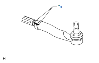
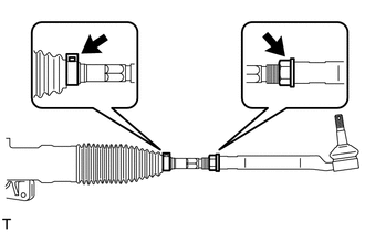
(1) Place matchmarks on the RH and LH tie rod ends and rack ends respectively where it can be easily seen. Text in Illustration
|
|
(2) Using a paper gauge, measure the distance from the RH and LH tie rod ends to the rack end screws.
HINT:
- Measure both the RH and LH sides.
- Make a note of the measured values.
|
(3) Remove the RH and LH boot clips from the rack boots. |
|
(4) Loosen the RH and LH lock nuts.
(5) Turn the RH and LH rack ends by the same amount (but in different directions) according to the steering angle value.
HINT:
One 360° turn of a rack end (1.5 mm (0.0591 in.) horizontal movement) is equal to a 12° change in steering angle.
(6) Tighten the RH and LH lock nuts to the specified torque.
Torque:
88 N·m {897 kgf·cm, 65 ft·lbf}
NOTICE:
Make sure that the difference in length between the RH and LH tie rod ends and rack end screws is within 1.5 mm (0.0591 in.).
(7) Install the RH and LH boot clips.
 Problem Symptoms Table
PROBLEM SYMPTOMS TABLE
HINT:
Use the table below to help determine the cause of problem symptoms. If multiple
suspected areas are listed, the potential causes of the symptoms are listed in order
...
 On-vehicle Inspection
ON-VEHICLE INSPECTION
PROCEDURE
1. INSPECT STEERING WHEEL FREE PLAY
(a) Stop the vehicle and align the tires so that they face straight ahead.
(b) Gently turn the steering wheel right a ...
Other materials about Toyota 4Runner:
SRS Warning Light Remains ON
DESCRIPTION
The SRS warning light is located in the combination meter.
When the SRS is normal, the SRS warning light comes on for approximately 6 seconds
after the ignition switch is turned from off to ON, and then goes off automatically.
If there is a ma ...
System Description
SYSTEM DESCRIPTION
1. PUSH-BUTTON START DESCRIPTION
(a) The push-button start function uses a push-type engine switch, which the
driver can operate by merely carrying the key. This system consists primarily of
the power management control ECU, engine swi ...

0.0248