Toyota 4Runner: Adjustment
ADJUSTMENT
CAUTION / NOTICE / HINT
NOTICE:
If the wheel alignment has been adjusted, and if suspension or underbody components have been removed/installed or replaced, be sure to perform the following initialization procedure in order for the system to function normally:
- Perform zero point calibration of the yaw rate and acceleration sensor and the test mode inspection.
PROCEDURE
1. INSPECT TIRES
(a) Inspect the tires (See page .gif) ).
).
2. MEASURE VEHICLE HEIGHT
NOTICE:
Before inspecting the wheel alignment, adjust the vehicle height to the specification.
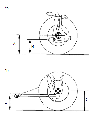
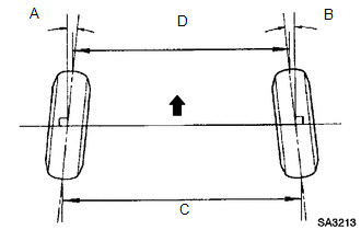
(a) Press down on the vehicle several times to stabilize the suspension, and then measure the vehicle height.
Text in Illustration|
*a |
Front Side |
|
*b |
Rear Side |
Measuring points:
A
Ground clearance of the center of the front wheel
B
Ground clearance of the center of the front adjusting cam bolt
C
Ground clearance of the center of the rear wheel
D
Ground clearance of the center of the rear lower control arm front side
If the vehicle height is not as specified, adjust the height by pressing down on the vehicle several times to stabilize the suspension.
Standard Vehicle Height (Unloaded Vehicle):
|
Vehicle Model |
Grade |
Front (A - B) |
Rear (C - D) |
|---|---|---|---|
|
GRN280L-GKAGKA |
SR5, SR5 Premium |
116.7 mm (4.59 in.) |
80.7 mm (3.18 in.) |
|
LIMITED |
117.2 mm (4.61 in.) |
85.4 mm (3.36 in.) |
|
|
GRN285L-GKAGKA |
SR5, SR5 Premium |
94.9 mm (3.74 in.) |
68.8 mm (2.71 in.) |
|
TRD Off-Road, TRD Off-Road Premium (w/o KDSS) |
95.6 mm (3.76 in.) |
69.8 mm (2.75 in.) |
|
|
TRD Off-Road, TRD Off-Road Premium (w/ KDSS) |
98.2 mm (3.87 in.) |
72.1 mm (2.84 in.) |
|
|
LIMITED |
97.6 mm (3.84 in.) |
72.5 mm (2.85 in.) |
NOTICE:
The standard value shown here is a value that is used for adjusting the wheel alignment and does not indicate the height of an actual vehicle.
3. INSPECT CAMBER, CASTER AND STEERING AXIS INCLINATION
|
(a) Install a camber-caster-kingpin gauge or place the front wheels on the center of a wheel alignment tester. Text in Illustration
|
|
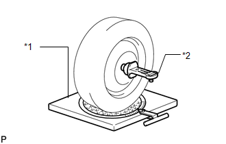
(b) Inspect the camber, caster and steering axis inclination.
Standard Camber Inclination (Unloaded Vehicle):
|
Vehicle Model |
Grade |
Camber Inclination |
Right-left Difference |
|---|---|---|---|
|
GRN280L-GKAGKA |
SR5, SR5 Premium |
-0°37' +/-30' (-0.62° +/-0.5°) |
30' (0.5°) or less |
|
LIMITED |
-0°38' +/-30' (-0.63° +/-0.5°) |
30' (0.5°) or less |
|
|
GRN285L-GKAGKA |
SR5, SR5 Premium |
-0°1' +/-30' (-0.02° +/-0.5°) |
30' (0.5°) or less |
|
TRD Off-Road, TRD Off-Road Premium (w/o KDSS) |
-0°3' +/-30' (-0.05° +/-0.5°) |
30' (0.5°) or less |
|
|
TRD Off-Road, TRD Off-Road Premium (w/ KDSS) |
-0°7' +/-30' (-0.12° +/-0.5°) |
30' (0.5°) or less |
|
|
LIMITED |
-0°6' +/-30' (-0.10° +/-0.5°) |
30' (0.5°) or less |
Standard Caster Inclination (Unloaded Vehicle):
|
Vehicle Model |
Grade |
Caster Inclination |
Right-left Difference |
|---|---|---|---|
|
GRN280L-GKAGKA |
SR5, SR5 Premium |
3°40' +/-30' (3.67° +/-0.5°) |
30' (0.5°) or less |
|
LIMITED |
3°50' +/-30' (3.83° +/-0.5°) |
30' (0.5°) or less |
|
|
GRN285L-GKAGKA |
SR5, SR5 Premium |
3°15' +/-30' (3.25° +/-0.5°) |
30' (0.5°) or less |
|
TRD Off-Road, TRD Off-Road Premium (w/o KDSS) |
3°16' +/-30' (3.27° +/-0.5°) |
30' (0.5°) or less |
|
|
TRD Off-Road, TRD Off-Road Premium (w/ KDSS) |
3°21' +/-30' (3.35° +/-0.5°) |
30' (0.5°) or less |
|
|
LIMITED |
3°22' +/-30' (3.37° +/-0.5°) |
30' (0.5°) or less |
Standard Steering Axis Inclination (Unloaded Vehicle):
|
Vehicle Model |
Grade |
Steering Axis Inclination |
|---|---|---|
|
GRN280L-GKAGKA |
SR5, SR5 Premium |
12°42' +/-30' (12.70° +/-0.5°) |
|
LIMITED |
12°44' +/-30' (12.73° +/-0.5°) |
|
|
GRN285L-GKAGKA |
SR5, SR5 Premium |
12°11' +/-30' (12.18° +/-0.5°) |
|
TRD Off-Road, TRD Off-Road Premium (w/o KDSS) |
12°12' +/-30' (12.20° +/-0.5°) |
|
|
TRD Off-Road, TRD Off-Road Premium (w/ KDSS) |
12°16' +/-30' (12.27° +/-0.5°) |
|
|
LIMITED |
12°15' +/-30' (12.25° +/-0.5°) |
4. ADJUST CAMBER AND CASTER
HINT:
After the camber has been adjusted, inspect the toe-in.
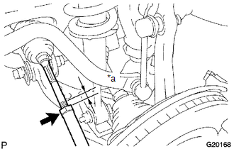
(a) Loosen the front adjusting cam bolt and rear adjusting cam nut.
(b) Turn the front adjusting cam and rear adjusting cam in both directions, and adjust the camber and caster to the center value.
HINT:
- The camber and caster should be as close as possible to the center value.
- Adjust the camber and caster within +/-30'.
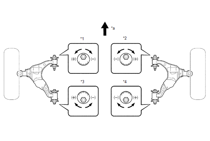 Text in Illustration
|
*1 |
Front Adjusting Cam LH |
*2 |
Front Adjusting Cam RH |
|
*3 |
Rear Adjusting Cam LH |
*4 |
Rear Adjusting Cam RH |
.png) |
Front |
- |
- |
(c) Read the adjustment chart (example).
Text in Illustration|
*1 |
Caster |
|
*2 |
Camber |
|
*3 |
Front Adjusting Cam |
|
*4 |
Rear Adjusting Cam |
|
*a |
Measured Value |
|
*b |
Standard Value |
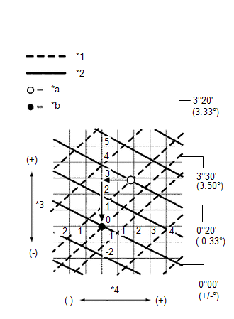
(1) Find the wheel alignment standard value applicable for the particular model.
(2) Mark the selected standard value on the adjustment chart.
Standard Value (Reference)|
Camber |
Caster |
|---|---|
|
0°00' (0.00°) |
3°30' (3.50°) |
(3) Mark the alignment value measured when the vehicle is unloaded on the adjustment chart.
Measured Value (Reference)|
Camber |
Caster |
|---|---|
|
-0°20' (-0.33°) |
3°20' (3.33°) |
(4) As shown in the chart, read the distance from the marked point to 0, and adjust the front and/ or rear adjusting cams accordingly.
Amount to Turn Adjusting Cams (by Gradation)|
Front Adjusting Cam |
Rear Adjusting Cam |
|---|---|
|
+3 |
+2 |
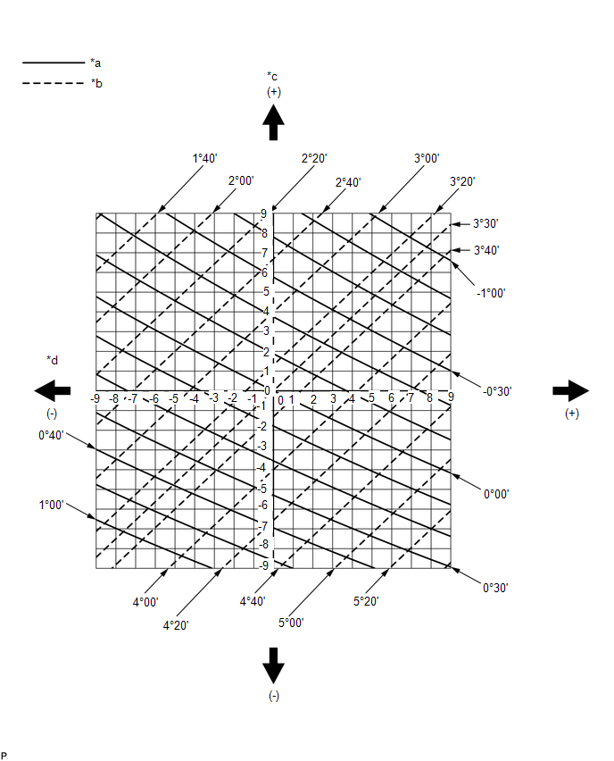 Text in Illustration
|
*a |
Camber |
*b |
Caster |
|
*c |
Front Cam Graduation |
*d |
Rear Cam Graduation |
5. INSPECT TOE-IN
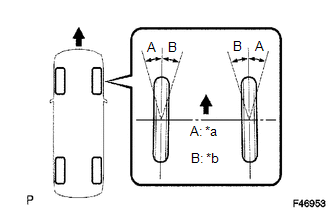
(a) Bounce the vehicle up and down at the corners to stabilize the suspension and inspect the toe-in.
Text in Illustration|
|
Front |
Standard Toe-in (Unloaded Vehicle):
|
Vehicle Model |
Grade |
Toe-in |
|---|---|---|
|
GRN280L-GKAGKA |
SR5, SR5 Premium |
A + B: 0°10' +/-0°9' (0.16° +/-0.15°) C - D: 2.35 +/-2 mm (0.09 +/-0.08 in.) |
|
LIMITED |
A + B: 0°10' +/-0°9' (0.16° +/-0.15°) C - D: 2.16 +/-2 mm (0.09 +/-0.08 in.) |
|
|
GRN285L-GKAGKA |
SR5, SR5 Premium |
A + B: 0°10' +/-0°9' (0.16° +/-0.15°) C - D: 2.29 +/-2 mm (0.09 +/-0.08 in.) |
|
TRD Off-Road, TRD Off-Road Premium (w/o KDSS) |
A + B: 0°10' +/-0°9' (0.16° +/-0.15°) C - D: 2.11 +/-2 mm (0.08 +/-0.08 in.) |
|
|
TRD Off-Road, TRD Off-Road Premium (w/ KDSS) |
A + B: 0°6' +/-0°9' (0.10° +/-0.15°) C - D: 1.49 +/-2 mm (0.06 +/-0.08 in.) |
|
|
LIMITED |
A + B: 0°8' +/-0°9' (0.14° +/-0.15°) C - D: 1.60 +/-2 mm (0.06 +/-0.08 in.) |
If the toe-in is not within the specified range, adjust it at the rack ends.
6. ADJUST TOE-IN
(a) Detach the rack boot set clips.
(b) Loosen the tie rod end lock nuts.
(c) Turn the right and left rack ends by an equal amount to adjust the toe-in to the center value.
(d) Check that the lengths of the right and left rack ends are approximately the same.
Standard difference:
0 +/-1 mm (0 +/-0.0394 in.) or less
Text in Illustration|
*a |
Length |
|
|
Lock Nut |
(e) Tighten the tie rod end lock nuts.
Torque:
88 N·m {897 kgf·cm, 65 ft·lbf}
(f) Place the boots on the seats and install the clips.
HINT:
Make sure that the boots are not twisted.
7. INSPECT WHEEL ANGLE
(a) Turn the steering wheel to the left and right full lock positions, and measure the turning angle.
Text in Illustration|
*a |
Inside |
|
*b |
Outside |
|
|
Front |
Standard Wheel Turning Angle (Unloaded Vehicle):
|
Vehicle Model |
Grade |
Inside Wheel Angle |
Outside Wheel Angle: Reference |
|---|---|---|---|
|
GRN280L-GKAGKA |
SR5, SR5 Premium |
29°48' to 32°48' (29.80° to 32.80°) |
29°33' (29.55°) |
|
LIMITED |
29°47' to 32°47' (29.78° to 32.78°) |
29°31' (29.52°) |
|
|
GRN285L-GKAGKA |
SR5, SR5 Premium |
30°20' to 33°20' (30.33° to 33.33°) |
29°28' (29.47°) |
|
TRD Off-Road, TRD Off-Road Premium (w/o KDSS) |
30°20' to 33°20' (30.33° to 33.33°) |
29°27' (29.45°) |
|
|
TRD Off-Road, TRD Off-Road Premium (w/ KDSS) |
30°17' to 33°17' (30.28° to 33.28°) |
29°23' (29.38°) |
|
|
LIMITED |
30°18' to 33°18' (30.30° to 33.30°) |
29°24' (29.40°) |
If the right and left inside wheel angles differ from the specified range, check the right and left rack end lengths.
8. PLACE FRONT WHEELS FACING STRAIGHT AHEAD
9. PERFORM YAW RATE SENSOR ZERO POINT CALIBRATION
HINT:
Perform the yaw rate sensor zero point calibration (See page
).
10. PERFORM INITIALIZATION
HINT:
Some systems need to be initialized after the wheel alignment is adjusted (See
page ).

 Front Suspension
...
Other materials about Toyota 4Runner:
AUTO LSD system (2WD models)
The AUTO LSD system aids traction by using the traction control system to
control engine performance and braking when one of the rear wheels begins to
spin.
The system should be used only when wheel spinning occurs in a ditch or rough
surface.
System o ...
Using the automatic air conditioning system
Press
.
The air conditioning system begins to operate. Air outlets and fan speed are
automatically adjusted according to the temperature setting.
Turn
clockwise to increases the
temperature and turn
counterclockwise to decreases the temperature o ...

0.0268