Toyota 4Runner: Front Differential Carrier Oil Seal(for 4wd)
Components
COMPONENTS
ILLUSTRATION
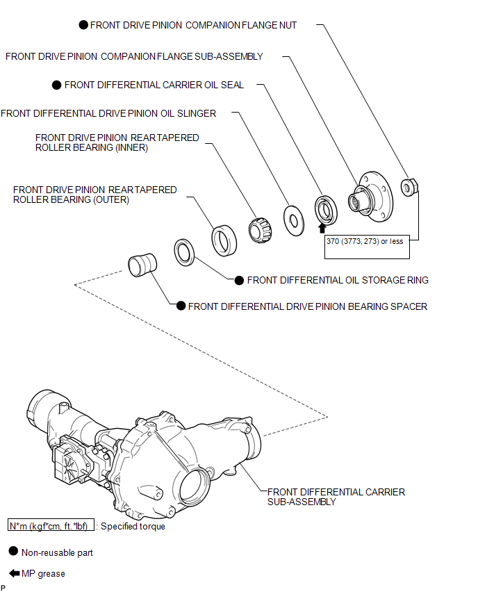
Replacement
REPLACEMENT
PROCEDURE
1. REMOVE FRONT DIFFERENTIAL CARRIER ASSEMBLY
(a) Remove the front differential carrier assembly (See page
.gif) ).
).
2. REMOVE FRONT DRIVE PINION COMPANION FLANGE NUT
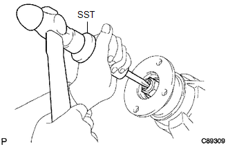
(a) Using SST and a hammer, loosen the staked part of the nut.
SST: 09930-00010
|
(b) Using SST to hold the companion flange, remove the nut. SST: 09330-00021 09330-00030 Text in Illustration
|
|
3. REMOVE FRONT DRIVE PINION COMPANION FLANGE SUB-ASSEMBLY
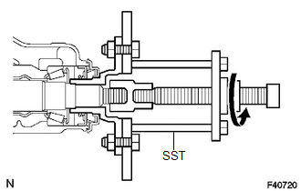
(a) Using SST, remove the companion flange.
SST: 09950-30012
09951-03010
09953-03010
09954-03010
09955-03030
09956-03020
NOTICE:
Before using SST (center bolt), apply hypoid gear oil to its threads and tip.
4. REMOVE FRONT DIFFERENTIAL CARRIER OIL SEAL
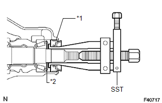
(a) Using SST, remove the oil seal.
SST: 09308-10010
Text in Illustration|
*1 |
Oil Seal |
|
*2 |
Oil Slinger |
5. REMOVE FRONT DIFFERENTIAL DRIVE PINION OIL SLINGER
6. REMOVE FRONT DRIVE PINION REAR TAPERED ROLLER BEARING
.png)
(a) Using SST, remove the roller bearing (inner).
SST: 09556-22010
|
(b) Using SST, tap out the roller bearing (outer). SST: 09308-00010 |
|
7. REMOVE FRONT DIFFERENTIAL OIL STORAGE RING
(a) Using a screwdriver and hammer, tap out the oil storage ring.
8. REMOVE FRONT DIFFERENTIAL DRIVE PINION BEARING SPACER
|
(a) Remove the bearing spacer. |
|
9. INSTALL FRONT DIFFERENTIAL DRIVE PINION BEARING SPACER
(a) Install a new bearing spacer.
HINT:
Install the spacer so that it is facing in the correct direction.
10. INSTALL FRONT DIFFERENTIAL OIL STORAGE RING
(a) Using a brass bar and hammer, tap in a new oil storage ring.
NOTICE:
Be careful not to damage the oil storage ring.
11. INSTALL FRONT DRIVE PINION REAR TAPERED ROLLER BEARING
.png)
(a) Using SST and a hammer, install the roller bearing (outer).
SST: 09316-60011
09316-00011
09316-00021
(b) Install the roller bearing (inner).
12. INSTALL FRONT DIFFERENTIAL DRIVE PINION OIL SLINGER
13. INSTALL FRONT DIFFERENTIAL CARRIER OIL SEAL
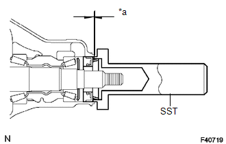
(a) Apply MP grease to the lip of a new oil seal.
(b) Using SST and a hammer, tap in the oil seal.
SST: 09554-22010
Oil seal depth:
3.9 to 4.8 mm (0.154 to 0.188 in.)
Text in Illustration|
*a |
Oil Seal Depth |
14. INSTALL FRONT DRIVE PINION COMPANION FLANGE SUB-ASSEMBLY
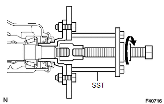
(a) Using SST, install the companion flange.
SST: 09950-30012
09951-03010
09953-03010
09954-03010
09955-03030
09956-03020
NOTICE:
Before using SST (center bolt), apply hypoid gear oil to its threads and tip.
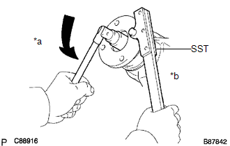
(b) Using SST to hold the companion flange, install the nut.
SST: 09330-00021
09330-00030
Torque:
370 N·m {3770 kgf·cm, 273 ft·lbf}
or less
15. INSPECT DIFFERENTIAL DRIVE PINION PRELOAD
(a) Using a torque wrench, measure the preload.
Standard Preload (at Starting):
|
Item |
Specified Condition |
|---|---|
|
New bearing |
0.98 to 1.57 N*m (10 to 16 kgf*cm, 8.7 to 13.9 in.*lbf) |
|
Used bearing |
0.49 to 0.78 N*m (5 to 8 kgf*cm, 4.3 to 6.9 in.*lbf) |
If the result is not as specified, adjust the preload.
Standard Total Preload (at Starting):
|
Item |
Specified Condition |
|---|---|
|
New bearing |
1.2 to 2.45 N*m (12 to 25 kgf*cm, 10.6 to 21.7 in.*lbf) |
|
Used bearing |
0.71 to 1.66 N*m (7.2 to 17 kgf*cm, 6.3 to 14.7 in.*lbf) |
16. STAKE FRONT DRIVE PINION COMPANION FLANGE FRONT NUT
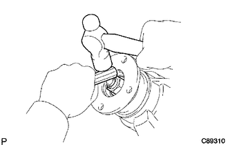
(a) Using a chisel and hammer, stake the nut.
17. INSTALL FRONT DIFFERENTIAL CARRIER ASSEMBLY
(a) Install the front differential carrier assembly (See page
.gif) ).
).
 Installation
INSTALLATION
PROCEDURE
1. INSTALL FRONT DIFFERENTIAL CARRIER ASSEMBLY
(a) Install the front No. 3 differential support with the 2 bolts.
Torque:
108 N·m {1101 kgf·cm, 80 ft·lbf}
(b) Install ...
 Front Differential Side Gear Shaft Oil Seal(for 4wd)
Components
COMPONENTS
ILLUSTRATION
Replacement
REPLACEMENT
CAUTION / NOTICE / HINT
HINT:
Use the same procedure for the RH and LH sides.
The procedure listed below is for the ...
Other materials about Toyota 4Runner:
Removal
REMOVAL
PROCEDURE
1. DISCONNECT CABLE FROM NEGATIVE BATTERY TERMINAL
CAUTION:
Wait at least 90 seconds after disconnecting the cable from the negative (-)
battery terminal to disable the SRS system.
NOTICE:
When disconnecting the cable, some systems ne ...
Engine (ignition) switch (vehicles with a smart key system)
Performing the following operations when carrying the electronic key on
your person starts the engine or changes “ENGINE START STOP” switch modes.
Starting the engine
Check that the parking brake is
set.
Check that the shift lever is
set in P.
...
0.0293

.png)
.png)