Toyota 4Runner: Adjustment
ADJUSTMENT
CAUTION / NOTICE / HINT
HINT:
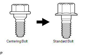
- Centering bolts are used to mount the door hinge to the vehicle body and door. The door cannot be adjusted with the centering bolts installed on it. Substitute the centering bolts with standard bolts when making adjustments.
- The specified torque for standard bolts is shown in the standard bolt
chart (See page
.gif) ).
).
PROCEDURE
1. INSPECT FRONT DOOR
(a) Check that the clearance measurements of areas A through H are within each standard range.
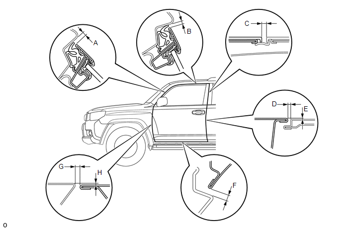
Standard:
|
Area |
Measurement |
Area |
Measurement |
|---|---|---|---|
|
A |
4.1 to 7.1 mm (0.161 to 0.280 in.) |
B |
4.2 to 7.2 mm (0.165 to 0.283 in.) |
|
C |
3.4 to 6.4 mm (0.134 to 0.252 in.) |
D |
3.3 to 6.3 mm (0.130 to 0.248 in.) |
|
E |
-1.5 to 1.5 mm (-0.0591 to 0.0591 in.) |
F |
4.2 to 7.2 mm (0.165 to 0.283 in.) |
|
G |
3.0 to 6.0 mm (0.118 to 0.236 in.) |
H |
-1.5 to 1.5 mm (-0.0591 to 0.0591 in.) |
2. DISCONNECT CABLE FROM NEGATIVE BATTERY TERMINAL
CAUTION:
Wait at least 90 seconds after disconnecting the cable from the negative (-) battery terminal to disable the SRS system.
NOTICE:
When disconnecting the cable, some systems need to be initialized after the cable
is reconnected (See page ).
3. ADJUST FRONT DOOR
|
(a) Using SST, loosen the hinge bolts on the vehicle body and adjust the door position. SST: 09812-00010 |
|
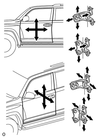
(b) Tighten the hinge bolts on the vehicle body after the adjustment.
Torque:
26 N·m {265 kgf·cm, 19 ft·lbf}
(c) Loosen the hinge bolts on the door and adjust the door position.
(d) Tighten the hinge bolts on the door after the adjustment.
Torque:
27 N·m {275 kgf·cm, 20 ft·lbf}
|
(e) Using a T40 "TORX" socket wrench, slightly loosen the striker mounting screws. |
|
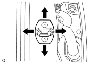
(f) Using a brass bar and hammer, hit the striker to adjust its position.
(g) Using a T40 "TORX" socket wrench, tighten the striker mounting screws after the adjustment.
Torque:
23 N·m {235 kgf·cm, 17 ft·lbf}
4. CONNECT CABLE TO NEGATIVE BATTERY TERMINAL
NOTICE:
When disconnecting the cable, some systems need to be initialized after the cable
is reconnected (See page ).
5. CHECK SRS WARNING LIGHT
(a) Check the SRS warning light (See page ).
 Disassembly
DISASSEMBLY
CAUTION / NOTICE / HINT
HINT:
Use the same procedure for both the RH and LH sides.
The procedure listed below is for the LH side.
PROCEDURE
1. DISCONNECT CABLE FROM ...
 Reassembly
REASSEMBLY
CAUTION / NOTICE / HINT
HINT:
Use the same procedure for both the RH and LH sides.
The procedure listed below is for the LH side.
PROCEDURE
1. INSTALL FRONT DOOR PANE ...
Other materials about Toyota 4Runner:
Security Horn Assembly
Components
COMPONENTS
ILLUSTRATION
Removal
REMOVAL
PROCEDURE
1. REMOVE AIR CLEANER CAP AND HOSE
2. REMOVE AIR CLEANER CASE SUB-ASSEMBLY
3. REMOVE SECURITY HORN ASSEMBLY
(a) Disconnect the connector.
...
Back-up Power Source Circuit
DESCRIPTION
The back-up power source circuit for the air conditioning amplifier assembly
is shown below. Power is supplied even after the ignition switch is turned off and
is used for diagnostic trouble code memory, etc.
WIRING DIAGRAM
CAUTION / NOTIC ...

0.0265