Toyota 4Runner: Disassembly
DISASSEMBLY
CAUTION / NOTICE / HINT
HINT:
- Use the same procedure for both the RH and LH sides.
- The procedure listed below is for the LH side.
PROCEDURE
1. DISCONNECT CABLE FROM NEGATIVE BATTERY TERMINAL
CAUTION:
Wait at least 90 seconds after disconnecting the cable from the negative (-) battery terminal to disable the SRS system.
NOTICE:
When disconnecting the cable, some systems need to be initialized after the cable
is reconnected (See page .gif) ).
).
2. REMOVE FRONT DOOR LOWER FRAME BRACKET GARNISH LH
|
(a) Detach the 2 clips to remove the front door lower frame bracket garnish LH. |
|
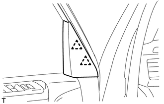
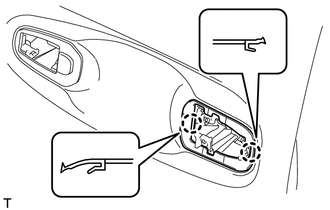
3. REMOVE NO. 2 DOOR INSIDE HANDLE BEZEL LH
|
(a) Using a moulding remover, detach the 3 claws to remove the No. 2 door inside handle bezel LH as shown in the illustration. Text in Illustration
|
|
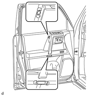
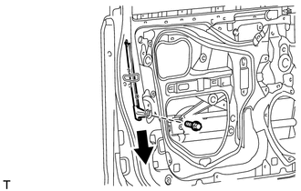
4. REMOVE FRONT DOOR TRIM BOARD SUB-ASSEMBLY LH
|
(a) Detach the 4 claws to remove the 2 door armrest caps. |
|
|
(b) Remove the 3 screws. |
|
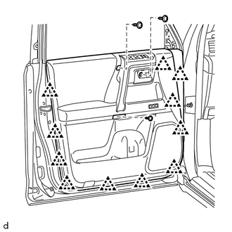
(c) Detach the 11 clips.
|
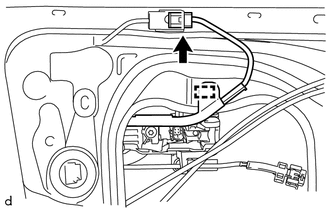
(d) Pull out the front door trim board sub-assembly LH in the direction indicated by the arrow shown in the illustration. |
|
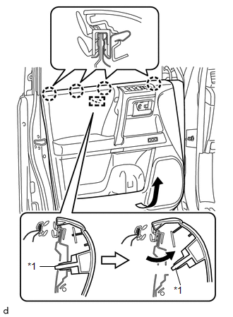
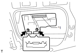
(e) Raise the front door trim board sub-assembly LH and detach the 4 claws and reference boss to remove the front door trim board sub-assembly LH together with the front door inner glass weatherstrip LH.
Text in Illustration|
*1 |
Reference Boss |
|
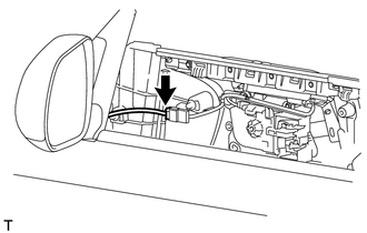
(f) Disconnect the connector. |
|
|
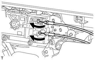
(g) Disconnect the front door lock remote control cable assembly LH and front door inside locking cable assembly LH. |
|
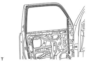
5. REMOVE FRONT DOOR INNER GLASS WEATHERSTRIP LH
|
(a) Using a screwdriver, detach the 4 claws to remove the front door inner glass weatherstrip LH from the front door trim board sub-assembly LH as shown in the illustration. |
|
6. REMOVE NO. 1 INTERIOR ILLUMINATION LIGHT ASSEMBLY (w/ Intuitive Parking Assist System)
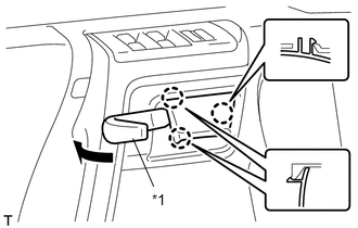
7. REMOVE COURTESY LIGHT ASSEMBLY LH
8. REMOVE MULTIPLEX NETWORK MASTER SWITCH ASSEMBLY (for Driver Side)
9. REMOVE DOOR CONTROL SWITCH ASSEMBLY (for Front Passenger Side)
10. REMOVE POWER WINDOW REGULATOR SWITCH ASSEMBLY (for Front Passenger Side)
11. REMOVE SEAT MEMORY SWITCH (w/ Seat Position Memory System)
12. REMOVE FRONT NO. 1 SPEAKER ASSEMBLY
13. REMOVE SIDE AIRBAG SENSOR ASSEMBLY LH
14. REMOVE FRONT DOOR SERVICE HOLE COVER LH
|
(a) Remove the bolt. |
|
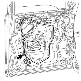
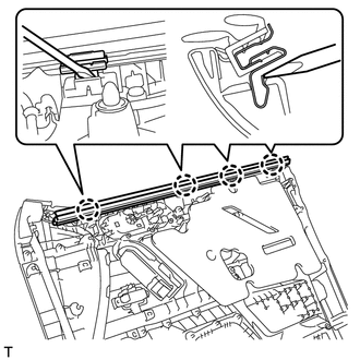
(b) Detach the 2 clamps and move the front door wire out of the way to remove the front door service hole cover LH.
HINT:
Remove any remaining butyl tape from the door panel.
15. REMOVE OUTER REAR VIEW MIRROR ASSEMBLY LH
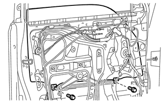
16. REMOVE FRONT DOOR GLASS SUB-ASSEMBLY LH
(a) Connect the multiplex network master switch assembly (for Driver Side).
(b) Connect the power window regulator switch assembly (for Front Passenger Side).
(c) Connect the cable to the negative (-) battery terminal.
(d) Move the front door glass sub-assembly so that the front door glass bolts can be seen.
(e) Disconnect the cable from the negative (-) battery terminal.
CAUTION:
Wait at least 90 seconds after disconnecting the cable from the negative (-) battery terminal to disable the SRS system.
NOTICE:
When disconnecting the cable, some systems need to be initialized after the cable
is reconnected (See page ).
(f) Disconnect the multiplex network master switch assembly (for Driver Side).
(g) Disconnect the power window regulator switch assembly (for Front Passenger Side).
|
(h) Remove the 2 bolts. NOTICE: Be careful when removing the bolts as the glass may fall and become damaged. |
|
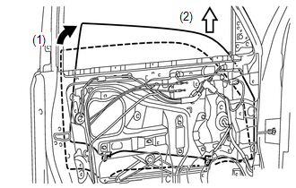
|
(i) Remove the front door glass sub-assembly LH as indicated by the arrows in the order shown in the illustration. NOTICE: Do not damage the front door glass sub-assembly LH. |
|
17. REMOVE FRONT DOOR WINDOW REGULATOR SUB-ASSEMBLY LH
|
(a) Disconnect the connector. |
|
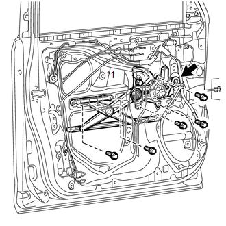
(b) Loosen the temporary bolt.
Text in Illustration|
*1 |
Temporary Bolt |
NOTICE:
Do not remove the temporary bolt. If the temporary bolt is removed, the front door window regulator sub-assembly LH may fall and cause damage.
(c) Remove the 5 bolts.
(d) Remove the front door window regulator sub-assembly LH.
(e) Remove the temporary bolt from the front door window regulator sub-assembly LH.
18. REMOVE FRONT POWER WINDOW REGULATOR MOTOR ASSEMBLY LH
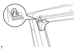
19. REMOVE DOOR FRAME GARNISH LH
|
(a) Detach the clip to remove the door frame garnish LH. |
|
20. REMOVE FRONT DOOR GLASS RUN LH
|
(a) Remove the front door glass run LH. |
|
21. REMOVE FRONT DOOR REAR LOWER FRAME SUB-ASSEMBLY LH
|
(a) Remove the bolt and front door rear lower frame sub-assembly LH as shown in the illustration. |
|
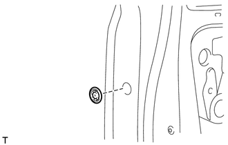
22. REMOVE FRONT DOOR OUTSIDE HANDLE COVER WITH LOCK CYLINDER ASSEMBLY (for Driver Side)
|
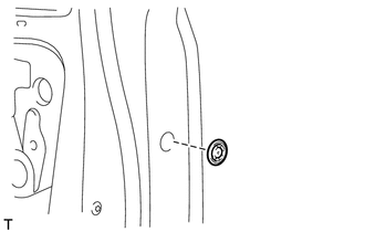
(a) Remove the hole plug. |
|
|
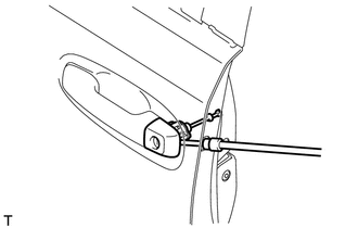
(b) Using a T30 "TORX" socket wrench, loosen the screw to remove the front door outside handle cover with lock cylinder assembly. HINT: The screw cannot be removed because it is integrated into the front door outside handle frame sub-assembly. |
|
23. REMOVE FRONT DOOR OUTSIDE HANDLE COVER LH (for Driver Side)
|
(a) Using a screwdriver, detach the claw to remove the front door outside handle cover LH from the lock cylinder assembly. HINT: Tape the screwdriver tip before use. |
|
24. REMOVE FRONT DOOR OUTSIDE HANDLE COVER RH (for Front Passenger Side)
|
(a) Remove the hole plug. |
|
|
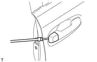
(b) Using a T30 "TORX" socket wrench, loosen the screw to remove the front door outside handle cover RH. HINT: The screw cannot be removed because it is integrated into the front door outside handle frame sub-assembly. |
|
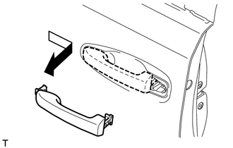
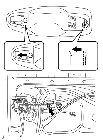
25. REMOVE FRONT DOOR OUTSIDE HANDLE ASSEMBLY LH
(a) w/ Smart Key System:
|
(1) Detach the 2 claws. |
|
(2) Disconnect the connector.
|
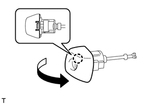
(b) Move the lever in the direction indicated by the arrow in the illustration. |
|
|
(c) Remove the front door outside handle assembly LH as shown in the illustration. |
|
26. REMOVE FRONT DOOR FRONT OUTSIDE HANDLE PAD LH
|
(a) Detach the guide and 2 claws to remove the front door front outside handle pad LH. |
|
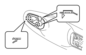
27. REMOVE FRONT DOOR REAR OUTSIDE HANDLE PAD LH
|
(a) Detach the 2 claws to remove the front door rear outside handle pad LH. |
|
28. REMOVE FRONT DOOR LOCK ASSEMBLY LH
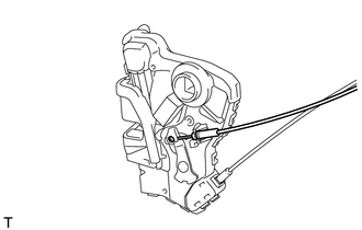
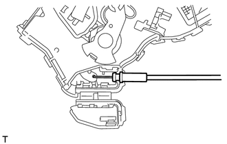
29. REMOVE FRONT DOOR LOCK REMOTE CONTROL CABLE ASSEMBLY LH
|
(a) Remove the front door lock remote control cable assembly LH from the front door lock assembly LH. |
|
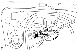
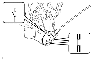
30. REMOVE FRONT DOOR INSIDE LOCKING CABLE ASSEMBLY LH
|
(a) Using a screwdriver, detach the 3 claws to open the cover. HINT: Tape the screwdriver tip before use. |
|
|
(b) Remove the front door inside locking cable assembly LH from the front door lock assembly LH. |
|
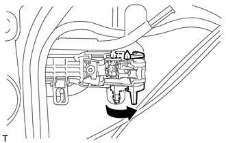
31. REMOVE FRONT DOOR OUTSIDE HANDLE FRAME SUB-ASSEMBLY LH
(a) w/ Smart Key System:
|
(1) Disconnect the connector. |
|
(2) Detach the clamp.
|
(b) Using a T30 "TORX" socket wrench, loosen the screw. |
|
(c) Slide the front door outside handle frame sub-assembly LH to detach the door handle nut and claw of the front door outside handle frame sub-assembly LH. Then remove the front door outside handle frame sub-assembly LH.
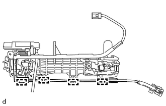
32. REMOVE FRONT DOOR NO. 2 WIRE LH (w/ Smart Key System)
|
(a) Detach the 4 clamps to remove the front door No. 2 wire LH. |
|
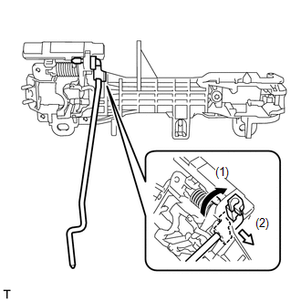
33. REMOVE FRONT DOOR LOCK OPEN ROD LH
|
(a) Remove the front door lock open rod LH as indicated by the arrows in the order shown in the illustration. |
|
34. REMOVE FRONT DOOR NO. 2 STIFFENER CUSHION
|
(a) Remove the 2 bolts. Text in Illustration
|
|
(b) Detach the 2 clamps to remove the front door No. 2 stiffener cushion.
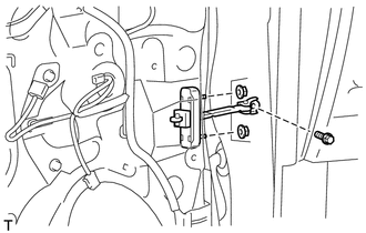
35. REMOVE FRONT DOOR CHECK ASSEMBLY LH
|
(a) Remove the bolt, 2 nuts and front door check assembly LH. |
|
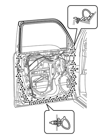
36. REMOVE FRONT DOOR WEATHERSTRIP LH
|
(a) Using a clip remover, detach the 21 clips to remove the front door weatherstrip LH. |
|
37. REMOVE FRONT DOOR BELT MOULDING LH
38. REMOVE FRONT DOOR REAR WINDOW FRAME MOULDING LH
39. REMOVE NO. 1 BLACK OUT TAPE LH
40. REMOVE FRONT DOOR OUTSIDE STRIPE LH
41. REMOVE FRONT DOOR LOWER OUTSIDE STRIPE LH
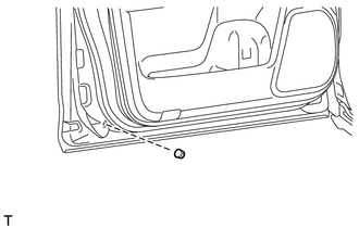
42. REMOVE FRONT DOOR PANEL CUSHION
|
(a) Using a clip remover, detach the claw to remove the front door panel cushion. |
|
 Components
COMPONENTS
ILLUSTRATION
ILLUSTRATION
ILLUSTRATION
ILLUSTRATION
...
 Adjustment
ADJUSTMENT
CAUTION / NOTICE / HINT
HINT:
Centering bolts are used to mount the door hinge to the vehicle body
and door. The door cannot be adjusted with the centering bolts installed ...
Other materials about Toyota 4Runner:
Reservoir Level Switch Disconnected (C1453,C1454)
DESCRIPTION
The brake fluid level warning switch sends the appropriate signal to the skid
control ECU when the brake fluid level drops.
DTC Code
DTC Detection Condition
Trouble Area
C1453
With th ...
Headlight Dimmer Switch Circuit
DESCRIPTION
The main body ECU receives the following signals:
Headlight dimmer switch tail, head, AUTO*, high or high flash signal
Front fog light switch signal
*: w/ Automatic Light Control System
WIRING DIAGRAM
PROCEDU ...

0.0069