Toyota 4Runner: Adjustment
ADJUSTMENT
PROCEDURE
1. INSPECT SHIFT LEVER POSITION
(a) When moving the shift lever from P to R with the ignition switch to on (IG) and the brake pedal depressed, make sure that it moves smoothly and correctly into position.
(b) Check that the shift lever does not stop when moving the shift lever from R to P, and check that the shift lever does not stick when moving the shift lever from D to S.
(c) Start the engine and make sure that the vehicle moves forward after moving the shift lever from N to D and moves in reverse after moving the shift lever to R.
If the operation cannot be performed as specified, inspect the park/neutral position switch assembly and check the transmission floor shift assembly installation condition.
2. ADJUST SHIFT LEVER POSITION
(a) Remove the rear console box (See page .gif) ).
).
(b) Move the shift lever to N.
|
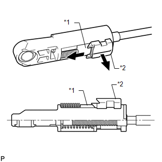
(c) Slide the slider in the direction shown in the illustration and pull out the lock piece. Text in Illustration
|
|
|
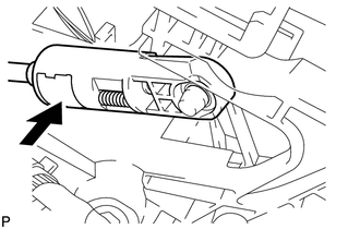
(d) Push the lock piece into the adjuster case and lock it. NOTICE: Make sure that the lock piece is completely locked by the slider. |
|
(e) Install the rear console box (See page ).
 Inspection
INSPECTION
PROCEDURE
1. INSPECT TRANSMISSION CONTROL SWITCH
(a) Measure the resistance according to the value(s) in the table below.
Standard Resistance:
Tester Connection
...
 Installation
INSTALLATION
PROCEDURE
1. INSTALL NO. 1 CONSOLE BOX MOUNTING BRACKET
(a) Install the console box mounting bracket with the 2 screws.
2. INSTALL SHIFT LEVER ASSEMBLY
(a) Install the transmission ...
Other materials about Toyota 4Runner:
System Description
SYSTEM DESCRIPTION
1. DESCRIPTION
(a) System description
In the KDSS (Kinetic Dynamic Suspension System), a cylinder is installed to each
of the front and rear stabilizer bars. The front and rear cylinder upper chambers
and the front and rear lower cham ...
Terminals Of Ecu
TERMINALS OF ECU
1. CHECK CERTIFICATION ECU
(a) Disconnect the F79 certification ECU connector.
(b) Measure the voltage and resistance according to the value(s) in the table
below.
Terminal No. (Symbol)
Wiring Color
Ter ...

0.0112