Toyota 4Runner: Navigation Receiver Assembly Power Source Circuit
DESCRIPTION
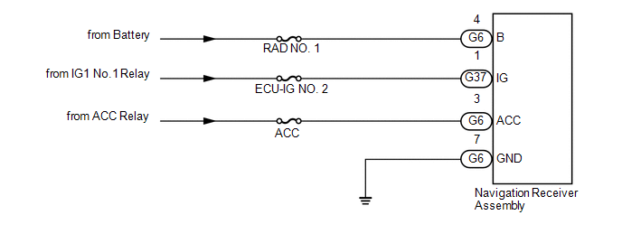
This is the power source circuit to operate the navigation receiver assembly.
WIRING DIAGRAM
CAUTION / NOTICE / HINT
NOTICE:
Inspect the fuses for circuits related to this system before performing the following inspection procedure.
PROCEDURE
|
1. |
CHECK HARNESS AND CONNECTOR (NAVIGATION RECEIVER ASSEMBLY - BATTERY, BODY GROUND) |
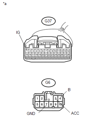
(a) Disconnect the G6 and G37 navigation receiver assembly connectors.
(b) Measure the resistance according to the value(s) in the table below .
Standard Resistance:
|
Tester Connection |
Condition |
Specified Condition |
|---|---|---|
|
G6-7 (GND) - Body ground |
Always |
Below 1 Ω |
|
(c) Measure the voltage according to the value(s) in the table below. Standard Voltage:
|
|
| OK | .gif) |
PROCEED TO NEXT SUSPECTED AREA SHOWN IN PROBLEM SYMPTOMS TABLE |
| NG | |
REPAIR OR REPLACE HARNESS OR CONNECTOR |
 Stereo Component Amplifier Power Source Circuit
DESCRIPTION
This circuit provides power to the stereo component amplifier assembly.
WIRING DIAGRAM
CAUTION / NOTICE / HINT
NOTICE:
Inspect the fuses for circuits related to this system before p ...

Other materials about Toyota 4Runner:
Security Indicator Light Circuit
DESCRIPTION
When the engine immobiliser system is set, the security indicator light
blinks continuously, but does not illuminate if the engine immobiliser system
is not set.
WIRING DIAGRAM
CAUTION / NOTICE / HINT
NOTICE:
When the tr ...
System Description
SYSTEM DESCRIPTION
CAUTION:
If using a pacemaker, be sure to read the manual of the pacemaker before using
the key, as the radio waves of the key may affect the pacemaker.
1. SMART KEY SYSTEM DESCRIPTION
(a) In addition to conventional mechanical key and ...

0.0068