Toyota 4Runner: Air Conditioning Compressor Magnetic Clutch Circuit
DESCRIPTION
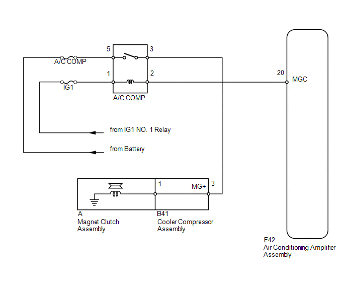
When the air conditioning amplifier assembly is turned on, a magnet clutch assembly ON signal is sent from the MGC terminal of the air conditioning amplifier assembly. Then, the A/C COMP relay turns on to operate the magnet clutch assembly.
WIRING DIAGRAM
CAUTION / NOTICE / HINT
NOTICE:
Inspect the fuses for circuits related to this system before performing the following inspection procedure.
PROCEDURE
|
1. |
INSPECT MAGNET CLUTCH RELAY (A/C COMP) |
|
(a) Remove the A/C COMP relay from the engine room No. 1 relay block, junction block. |
|
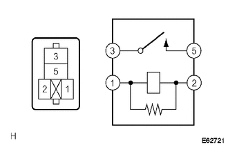
(b) Measure the resistance according to the value(s) in the table below.
Standard Resistance:
|
Tester Connection |
Condition |
Specified Condition |
|---|---|---|
|
3 - 5 |
Battery voltage is not applied to terminals 1 and 2 |
10 kΩ or higher |
|
Battery voltage is applied to terminals 1 and 2 |
Below 1 Ω |
| NG | .gif) |
REPLACE MAGNET CLUTCH RELAY (A/C COMP) |
|
.gif)
|
2. |
INSPECT COOLER COMPRESSOR ASSEMBLY |
|
(a) Remove the cooler compressor assembly (See page
|
|
.gif) ).
).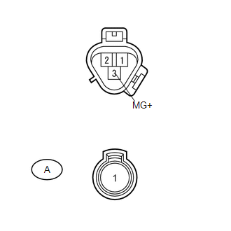
(b) Disconnect the A magnet clutch connector.
(c) Measure the resistance according to the value(s) in the table below.
Standard Resistance:
|
Tester Connection |
Condition |
Specified Condition |
|---|---|---|
|
3 (MG+) - A-1 |
Always |
Below 1 Ω |
|
3 (MG+) - Body ground |
Always |
10 kΩ or higher |
| NG | |
REPLACE COOLER COMPRESSOR ASSEMBLY |
|
|
3. |
INSPECT MAGNETIC CLUTCH ASSEMBLY |
|
(a) Reconnect the A magnet clutch connector. |
|
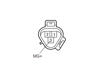
(b) Apply battery voltage to the magnet clutch assembly and check the operation of the magnet clutch assembly.
OK:
|
Measurement Condition |
Specified Condition |
|---|---|
|
Battery positive (+) → Terminal 3 (MG+) Battery negative (-) → Body ground |
Magnet clutch assembly operating sound can be heard, and magnetic clutch hub and rotor lock. |
| NG | |
REPLACE MAGNET CLUTCH ASSEMBLY |
|
|
4. |
CHECK HARNESS AND CONNECTOR (ENGINE ROOM NO. 1 RELAY BLOCK, JUNCTION BLOCK - BATTERY) |
|
(a) Remove the A/C COMP relay from the engine room No. 1 relay block, junction block. |
|
(b) Measure the voltage according to the value(s) in the table below.
Standard Voltage:
|
Tester Connection |
Switch Condition |
Specified Condition |
|---|---|---|
|
A/C COMP relay terminal 1 - Body ground |
Ignition switch ON |
11 to 14 V |
|
A/C COMP relay terminal 5 - Body ground |
Always |
11 to 14 V |
|
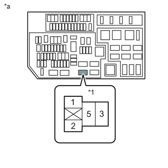
*1 |
A/C COMP Relay |
|
*a |
Component without relay installed (Engine Room No. 1 Relay Block, Junction Block) |
| NG | |
REPAIR OR REPLACE HARNESS OR CONNECTOR |
|
|
5. |
CHECK HARNESS AND CONNECTOR (AIR CONDITIONING AMPLIFIER - BATTERY) |
|
(a) Disconnect the F42 amplifier connector. |
|
(b) Measure the voltage according to the value(s) in the table below.
Standard Voltage:
|
Tester Connection |
Switch Condition |
Specified Condition |
|---|---|---|
|
F42-20 (MGC) - Body ground |
Ignition switch off |
Below 1 V |
|
F42-20 (MGC) - Body ground |
Ignition switch ON |
11 to 14 V |
|
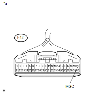
*a |
Front view of wire harness connector (to Air Conditioning Amplifier Assembly) |
| NG | |
REPAIR OR REPLACE HARNESS OR CONNECTOR |
|
|
6. |
CHECK HARNESS AND CONNECTOR (ENGINE ROOM NO. 1 RELAY BLOCK, JUNCTION BLOCK - COOLER COMPRESSOR) |
(a) Remove the A/C COMP relay from the engine room No. 1 relay block, junction block.
(b) Disconnect the B41 compressor connector.
(c) Measure the resistance according to the value(s) in the table below.
Standard Resistance:
|
Tester Connection |
Condition |
Specified Condition |
|---|---|---|
|
A/C COMP relay terminal 3 - B41-3 (MG+) |
Always |
Below 1 Ω |
|
B41-3 (MG+) - Body ground |
Always |
10 kΩ or higher |
| OK | |
PROCEED TO NEXT SUSPECTED AREA SHOWN IN PROBLEM SYMPTOMS TABLE |
| NG | |
REPAIR OR REPLACE HARNESS OR CONNECTOR |
 Air Conditioning Control Panel Circuit
DESCRIPTION
This circuit consists of the heater control assembly and air conditioning amplifier
assembly. When the heater control assembly is operated, signals are transmitted
to the air conditio ...
Other materials about Toyota 4Runner:
Speaker Circuit
DESCRIPTION
If there is a short in a speaker circuit, the radio and display receiver assembly
detects it and stops output to the speakers.
Thus sound cannot be heard from the speakers even if there is no malfunction
in the radio and display receiver asse ...
Diagnostic Trouble Code Chart
DIAGNOSTIC TROUBLE CODE CHART
HINT:
If a trouble code is output during the DTC check, inspect the trouble areas listed
for that code. For details of the code, refer to the "See page" below.
Steering Lock System
DTC Code
De ...

0.0163