Toyota 4Runner: Air Inlet Damper Control Servo Motor Circuit (B1442/42)
DESCRIPTION
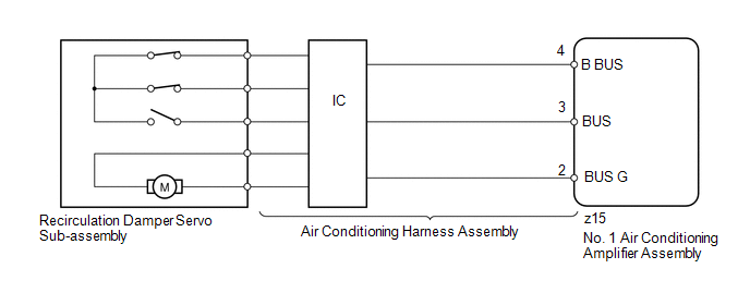
The recirculation damper servo sub-assembly sends pulse signals to inform the No. 1 air conditioning amplifier assembly of the damper position. The No. 1 air conditioning amplifier assembly activates the motor (normal or reverse) based on the signals to move the air inlet damper to any position, which controls the intake air settings (fresh, fresh/recirculation and recirculation).
HINT:
Confirm that no mechanical problem is present because this trouble code may be stored when either a damper link or damper is mechanically locked.
|
DTC Code |
DTC Detection Condition |
Trouble Area |
|---|---|---|
|
B1442/42 |
The air inlet damper position does not change when the No. 1 air conditioning amplifier assembly operates the recirculation damper servo sub-assembly. |
|
WIRING DIAGRAM
PROCEDURE
|
1. |
READ VALUE USING TECHSTREAM (RECIRCULATION DAMPER SERVO) |
(a) Use the Data List to check if the recirculation damper servo sub-assembly
is functioning properly (See page .gif) ).
).
Air Conditioner
|
Tester Display |
Measurement Item/Range |
Normal Condition |
Diagnostic Note |
|---|---|---|---|
|
Air Inlet Damper Targ Pulse |
Recirculation damper servo sub-assembly target pulse / Min.: 0, Max.: 255 |
7 (pulse): Recirculation 28 (pulse): Fresh |
- |
|
Air Inlet Damper Actual Pulse |
Recirculation damper servo sub-assembly actual pulse / Min.: 0, Max.: 255 |
7 (pulse): Recirculation 28 (pulse): Fresh |
- |
OK:
The display is as specified in the normal condition column.
Result|
Result |
Proceed to |
|---|---|
|
OK (When troubleshooting according to problem symptoms table) |
A |
|
OK (When troubleshooting according to the DTC) |
B |
|
NG |
C |
| A | .gif) |
PROCEED TO NEXT SUSPECTED AREA SHOWN IN PROBLEM SYMPTOMS TABLE |
| B | |
REPLACE NO. 1 AIR CONDITIONING AMPLIFIER ASSEMBLY |
|
.gif)
|
2. |
PERFORM ACTIVE TEST USING TECHSTREAM (RECIRCULATION DAMPER SERVO) |
(a) Select the Active Test, use the Techstream to generate a control command,
and then check that the recirculation damper servo sub-assembly operates (See page
).
Air Conditioner
|
Tester Display |
Test Part |
Control Range |
Diagnostic Note |
|---|---|---|---|
|
Air Inlet Damper Targ Pulse |
Recirculation damper servo sub-assembly target pulse |
Min.: 0, Max.: 255 |
- |
OK:
Recirculation damper servo sub-assembly operates normally.
| OK | |
REPLACE NO. 1 AIR CONDITIONING AMPLIFIER ASSEMBLY |
|
|
3. |
REPLACE RECIRCULATION DAMPER SERVO SUB-ASSEMBLY |
(a) Replace the recirculation damper servo sub-assembly (See page
).
HINT:
Since the recirculation damper servo sub-assembly cannot be inspected while it is removed from the vehicle, replace the recirculation damper servo sub-assembly with a new or normally functioning one.
|
|
4. |
CHECK FOR DTC |
(a) Clear the DTCs (See page ).
(b) Check for DTCs (See page ).
OK:
DTC B1442 is not output.
| OK | |
END (RECIRCULATION DAMPER SERVO SUB-ASSEMBLY IS FAULTY) |
|
|
5. |
REPLACE NO. 1 AIR CONDITIONING AMPLIFIER ASSEMBLY |
(a) Temporarily replace the No. 1 air conditioning amplifier assembly with a
new or normally functioning one (See page ).
|
|
6. |
CHECK FOR DTC |
(a) Clear the DTCs (See page ).
(b) Check for DTCs (See page ).
OK:
DTC B1442 is not output.
| OK | |
END (NO. 1 AIR CONDITIONING AMPLIFIER ASSEMBLY IS FAULTY) |
| NG | |
REPLACE AIR CONDITIONING HARNESS ASSEMBLY |
 Compressor Lock Sensor Circuit (B1422/22)
SYSTEM DESCRIPTION
The ECM sends the engine speed signal to the air conditioning amplifier assembly
via CAN communication.
The air conditioning amplifier assembly reads the difference between comp ...
 Air Outlet Damper Control Servo Motor Circuit (B1443/43)
DESCRIPTION
The damper servo sub-assembly (mode damper servo) sends pulse signals to inform
the No. 1 air conditioning amplifier assembly of the damper position. The No. 1
air conditioning amplif ...
Other materials about Toyota 4Runner:
Installation
INSTALLATION
CAUTION / NOTICE / HINT
HINT:
A bolt without a torque specification is shown in the standard bolt chart (See
page ).
PROCEDURE
1. INSTALL SIDE AUTO STEP CONTROLLER ECU ASSEMBLY
(a) Engage the guide and install the side auto step controlle ...
ECU Power Source Circuit
DESCRIPTION
This circuit provides power to operate the transponder key ECU assembly.
WIRING DIAGRAM
CAUTION / NOTICE / HINT
NOTICE:
Inspect the fuses for circuits related to this system before performing the following
inspection procedure.
PROCEDURE
...

0.0139