Toyota 4Runner: Air Outlet Damper Control Servo Motor Circuit (B1443/43)
DESCRIPTION
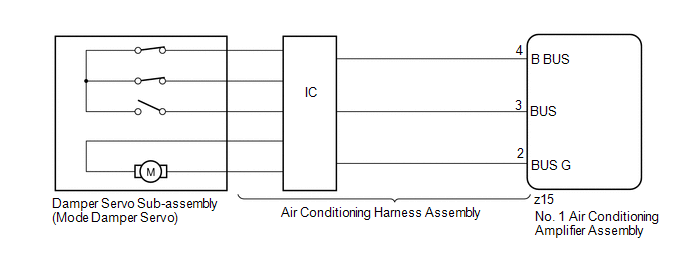
The damper servo sub-assembly (mode damper servo) sends pulse signals to inform the No. 1 air conditioning amplifier assembly of the damper position. The No. 1 air conditioning amplifier assembly activates the motor (normal or reverse) based on the signals to move the air outlet damper to any position, which controls the air outlet changes.
HINT:
Confirm that no mechanical problem is present because this trouble code may be stored when either a damper link or damper is mechanically locked.
|
DTC Code |
DTC Detection Condition |
Trouble Area |
|---|---|---|
|
B1443/43 |
The air outlet damper position does not change when the No. 1 air conditioning amplifier assembly operates the damper servo sub-assembly (mode damper servo). |
|
WIRING DIAGRAM
PROCEDURE
|
1. |
READ VALUE USING TECHSTREAM (MODE DAMPER SERVO) |
(a) Use the Data List to check if the damper servo sub-assembly (mode damper
servo) is functioning properly (See page .gif) ).
).
Air Conditioner
|
Tester Display |
Measurement Item/Range |
Normal Condition |
Diagnostic Note |
|---|---|---|---|
|
Air Outlet Servo Pulse (D) |
Damper servo sub-assembly (mode damper servo) actual pulse / Min.: 0, Max.: 255 |
15 (pulse): FACE 1 15 (pulse): FACE 2 41 (pulse): B/L 65 or 73 (pulse): FOOT 83 or 95 (pulse): F/D 113 (pulse): DEF |
- |
|
Air Outlet Servo Actu Pulse (D) |
Damper servo sub-assembly (mode damper servo) actual pulse / Min.: 0, Max.: 255 |
15 (pulse): FACE 1 15 (pulse): FACE 2 41 (pulse): B/L 65 or 73 (pulse): FOOT 83 or 95 (pulse): F/D 113 (pulse): DEF |
- |
OK:
The display is as specified in the normal condition column.
Result|
Result |
Proceed to |
|---|---|
|
OK (When troubleshooting according to problem symptoms table) |
A |
|
OK (When troubleshooting according to the DTC) |
B |
|
NG |
C |
| A | .gif) |
PROCEED TO NEXT SUSPECTED AREA SHOWN IN PROBLEM SYMPTOMS TABLE |
| B | |
REPLACE NO. 1 AIR CONDITIONING AMPLIFIER ASSEMBLY |
|
.gif)
|
2. |
PERFORM ACTIVE TEST USING TECHSTREAM (MODE DAMPER SERVO) |
(a) Select the Active Test, use the Techstream to generate a control command,
and then check that the damper servo sub-assembly (mode damper servo) operates (See
page ).
Air Conditioner
|
Tester Display |
Test Part |
Control Range |
Diagnostic Note |
|---|---|---|---|
|
Air Outlet Servo Pulse (D) |
Damper servo sub-assembly (mode damper servo) pulse |
Min.: 0, Max.: 255 |
- |
OK:
Damper servo sub-assembly (mode damper servo) operates normally.
| OK | |
REPLACE NO. 1 AIR CONDITIONING AMPLIFIER ASSEMBLY |
|
|
3. |
REPLACE DAMPER SERVO SUB-ASSEMBLY (MODE DAMPER SERVO) |
(a) Replace the damper servo sub-assembly (mode damper servo) (See page
).
HINT:
Since the damper servo sub-assembly (mode damper servo) cannot be inspected while it is removed from the vehicle, replace the damper servo sub-assembly (mode damper servo) with a new or normally functioning one.
|
|
4. |
CHECK FOR DTC |
(a) Clear the DTCs (See page ).
(b) Check for DTCs (See page ).
OK:
DTC B1443 is not output.
| OK | |
END (DAMPER SERVO SUB-ASSEMBLY [MODE DAMPER SERVO] IS FAULTY) |
|
|
5. |
REPLACE NO. 1 AIR CONDITIONING AMPLIFIER ASSEMBLY |
(a) Temporarily replace the No. 1 air conditioning amplifier assembly with a
new or normally functioning one (See page ).
|
|
6. |
CHECK FOR DTC |
(a) Clear the DTCs (See page ).
(b) Check for DTCs (See page ).
OK:
DTC B1443 is not output.
| OK | |
END (NO. 1 AIR CONDITIONING AMPLIFIER ASSEMBLY IS FAULTY) |
| NG | |
REPLACE AIR CONDITIONING HARNESS ASSEMBLY |
 Air Inlet Damper Control Servo Motor Circuit (B1442/42)
DESCRIPTION
The recirculation damper servo sub-assembly sends pulse signals to inform the
No. 1 air conditioning amplifier assembly of the damper position. The No. 1 air
conditioning amplifier as ...
 Evaporator Temperature Sensor Circuit (B1413/13)
DESCRIPTION
The No. 1 cooler thermistor is installed on the evaporator in the air conditioning
unit to detect the temperature of the cooled air that has passed through the evaporator
and control ...
Other materials about Toyota 4Runner:
Rear Washer does not Operate
DESCRIPTION
The windshield wiper switch controls the rear washer motor and pump.
WIRING DIAGRAM
CAUTION / NOTICE / HINT
NOTICE:
Inspect the fuses for circuits related to this system before performing the following
inspection procedure.
PROCEDURE
...
Diagnostic Trouble Code Chart
DIAGNOSTIC TROUBLE CODE CHART
HINT:
If a DTC is output during the DTC check, check the parts listed in the
table below and proceed to the "See page" given.
*1: "Comes on" means the Malfunction Indicator Lamp (MIL) illumina ...

0.0068