Toyota 4Runner: Ambient Temperature Sensor Circuit (B1412/12)
DESCRIPTION
The cooler thermistor (ambient temperature sensor) is installed in the front part of the cooler condenser assembly to detect the ambient temperature and control the air conditioning auto mode. The sensor connected to the air conditioning amplifier assembly detects fluctuations in the ambient temperature. This data is used for controlling the room temperature. The sensor sends a signal to the air conditioning amplifier assembly. The resistance of the cooler thermistor (ambient temperature sensor) changes in accordance with the cooler thermistor temperature (ambient temperature). As the temperature decreases, the resistance increases. As the temperature increases, the resistance decreases.
The air conditioning amplifier assembly applies a voltage (5 V) to the cooler thermistor (ambient temperature sensor) and reads voltage changes as changes in the resistance of the cooler thermistor (ambient temperature sensor).
|
DTC Code |
DTC Detection Condition |
Trouble Area |
|---|---|---|
|
B1412/12 |
An open or short in the cooler thermistor (ambient temperature sensor) circuit. |
|
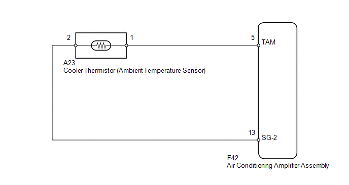
WIRING DIAGRAM
PROCEDURE
|
1. |
READ VALUE USING TECHSTREAM (AMBIENT TEMPERATURE SENSOR) |
(a) Use the Data List to check if the cooler thermistor (ambient temperature
sensor) is functioning properly (See page .gif) ).
).
Air Conditioner
|
Tester Display |
Measurement Item/Range |
Normal Condition |
Diagnostic Note |
|---|---|---|---|
|
Ambient Temp Sensor |
Cooler thermistor (ambient temperature sensor) / Min: -23.3°C (-9.94°F) Max: 65.95°C (150.71°F) |
Actual ambient temperature displayed |
Open in the circuit: -23.3°C (-9.94°F). Short in the circuit: 65.95°C (150.71°F). |
OK:
The display is as specified in the normal condition column.
Result|
Result |
Proceed to |
|---|---|
|
OK (When troubleshooting according to problem symptoms table) |
A |
|
OK (When troubleshooting according to the DTC) |
B |
|
NG |
C |
| A | .gif) |
PROCEED TO NEXT SUSPECTED AREA SHOWN IN PROBLEM SYMPTOMS TABLE |
| B | |
REPLACE AIR CONDITIONING AMPLIFIER ASSEMBLY |
|
.gif)
|
2. |
INSPECT COOLER THERMISTOR (AMBIENT TEMPERATURE SENSOR) |
(a) Remove the cooler thermistor (ambient temperature sensor) (See page
).
(b) Measure the resistance according to the value(s) in the table below.
Standard Resistance:
|
Tester Connection |
Condition |
Specified Condition |
|---|---|---|
|
1 - 2 |
10°C (50°F) |
3.00 to 3.73 kΩ |
|
15°C (59°F) |
2.45 to 2.88 kΩ |
|
|
20°C (68°F) |
1.95 to 2.30 kΩ |
|
|
25°C (77°F) |
1.60 to 1.80 kΩ |
|
|
30°C (86°F) |
1.28 to 1.47 kΩ |
|
|
35°C (95°F) |
1.00 to 1.22 kΩ |
|
|
40°C (104°F) |
0.80 to 1.00 kΩ |
|
|
45°C (113°F) |
0.65 to 0.85 kΩ |
|
|
50°C (122°F) |
0.50 to 0.70 kΩ |
|
|
55°C (131°F) |
0.44 to 0.60 kΩ |
|
|
60°C (140°F) |
0.36 to 0.50 kΩ |
|
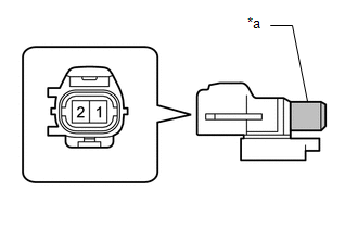
*a |
Sensing Portion |
|
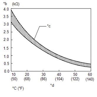
*b |
Resistance |
|
*c |
Allowable Range |
|
*d |
Temperature |
NOTICE:
- Even slightly touching the sensor may change the resistance value. Be sure to hold the connector of the sensor.
- When measuring, the sensor temperature must be the same as the ambient temperature.
HINT:
As the temperature increases, the resistance decreases (refer to the graph).
| NG | |
REPLACE COOLER THERMISTOR (AMBIENT TEMPERATURE SENSOR) |
|
|
3. |
CHECK HARNESS AND CONNECTOR (AMBIENT TEMPERATURE SENSOR - AIR CONDITIONING AMPLIFIER) |
(a) Disconnect the A23 sensor connector.
(b) Disconnect the F42 amplifier connector.
(c) Measure the resistance according to the value(s) in the table below.
Standard Resistance:
|
Tester Connection |
Condition |
Specified Condition |
|---|---|---|
|
A23-1 - F42-5 (TAM) |
Always |
Below 1 Ω |
|
A23-2 - F42-13 (SG-2) |
||
|
F42-5 (TAM) - Body ground |
Always |
10 kΩ or higher |
|
F42-13 (SG-2) - Body ground |
| OK | |
REPLACE AIR CONDITIONING AMPLIFIER ASSEMBLY |
| NG | |
REPAIR OR REPLACE HARNESS OR CONNECTOR |
 Room Temperature Sensor Circuit (B1411/11)
DESCRIPTION
The cooler thermistor (room temperature sensor) for the front seat is installed
in the instrument panel to detect the room temperature and control the heater and
air conditioner auto ...
 Compressor Lock Sensor Circuit (B1422/22)
SYSTEM DESCRIPTION
The ECM sends the engine speed signal to the air conditioning amplifier assembly
via CAN communication.
The air conditioning amplifier assembly reads the difference between comp ...
Other materials about Toyota 4Runner:
Inspection
INSPECTION
PROCEDURE
1. INSPECT REFRESHING SEAT SWITCH
Text in Illustration
*a
Component without harness connected
(Refreshing Seat Switch)
*b
Blower
*c
Heater
*d
...
Transmitter Battery(w/ Smart Key System)
Replacement
REPLACEMENT
CAUTION / NOTICE / HINT
NOTICE:
Take extra care when handling these precision electronic components.
PROCEDURE
1. REMOVE TRANSMITTER BATTERY
(a) Push the release hook knob and extract the emergency key.
...

0.0261