Toyota 4Runner: Room Temperature Sensor Circuit (B1411/11)
DESCRIPTION
The cooler thermistor (room temperature sensor) for the front seat is installed in the instrument panel to detect the room temperature and control the heater and air conditioner auto mode. The resistance of the room temperature sensor changes in accordance with the front room temperature. As the temperature decreases, the resistance increases. As the temperature increases, the resistance decreases.
The air conditioning amplifier assembly applies voltage (5 V) to the room temperature sensor and reads voltage changes as the resistance of the room temperature sensor changes. This sensor also sends the appropriate signals to the air conditioning amplifier assembly.
|
DTC Code |
DTC Detection Condition |
Trouble Area |
|---|---|---|
|
B1411/11 |
An open or short in the cooler thermistor (room temperature sensor) circuit. |
|
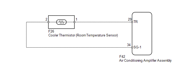
WIRING DIAGRAM
PROCEDURE
|
1. |
READ VALUE USING TECHSTREAM (ROOM TEMPERATURE SENSOR) |
(a) Use the Data List to check if the cooler thermistor (room temperature sensor)
is functioning properly (See page .gif) ).
).
Air Conditioner
|
Tester Display |
Measurement Item/Range |
Normal Condition |
Diagnostic Note |
|---|---|---|---|
|
Room Temperature Sensor |
Cooler thermistor (room temperature sensor) / Min.: -6.5°C (20.3°F) Max.: 57.25°C (135.05°F) |
Actual room temperature for front seat displayed |
Open in the circuit: -6.5°C (20.3°F). Short in the circuit: 57.25°C (135.05°F). |
OK:
The display is as specified in the normal condition column.
Result|
Result |
Proceed to |
|---|---|
|
OK (When troubleshooting according to problem symptoms table) |
A |
|
OK (When troubleshooting according to the DTC) |
B |
|
NG |
C |
| A | .gif) |
PROCEED TO NEXT SUSPECTED AREA SHOWN IN PROBLEM SYMPTOMS TABLE |
| B | |
REPLACE AIR CONDITIONING AMPLIFIER ASSEMBLY |
|
.gif)
|
2. |
INSPECT COOLER THERMISTOR (ROOM TEMPERATURE SENSOR) |
(a) Remove the cooler thermistor (room temperature sensor) (See page
).
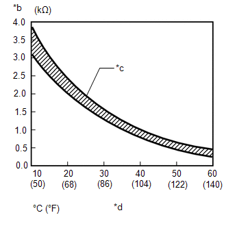
(b) Measure the resistance according to the value(s) in the table below.
Standard Resistance:
|
Tester Connection |
Condition |
Specified Condition |
|---|---|---|
|
1 - 2 |
10°C (50°F) |
3.00 to 3.73 kΩ |
|
15°C (59°F) |
2.45 to 2.88 kΩ |
|
|
20°C (68°F) |
1.95 to 2.30 kΩ |
|
|
25°C (77°F) |
1.60 to 1.80 kΩ |
|
|
30°C (86°F) |
1.28 to 1.47 kΩ |
|
|
35°C (95°F) |
1.00 to 1.22 kΩ |
|
|
40°C (104°F) |
0.80 to 1.00 kΩ |
|
|
45°C (113°F) |
0.65 to 0.85 kΩ |
|
|
50°C (122°F) |
0.50 to 0.70 kΩ |
|
|
55°C (131°F) |
0.44 to 0.60 kΩ |
|
|
60°C (140°F) |
0.36 to 0.50 kΩ |
|
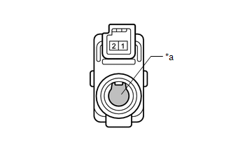
*a |
Sensing Portion |
|
*b |
Resistance |
|
*c |
Allowable Range |
|
*d |
Temperature |
NOTICE:
- Even slightly touching the sensor may change the resistance value. Be sure to hold the connector of the sensor.
- When measuring, the sensor temperature must be the same as the ambient temperature.
HINT:
As the temperature increases, the resistance decreases (refer to the graph).
| NG | |
REPLACE COOLER THERMISTOR (ROOM TEMPERATURE SENSOR) |
|
|
3. |
CHECK HARNESS AND CONNECTOR (ROOM TEMPERATURE SENSOR - AIR CONDITIONING AMPLIFIER) |
(a) Disconnect the F26 sensor connector.
(b) Disconnect the F42 amplifier connector.
(c) Measure the resistance according to the value(s) in the table below.
Standard Resistance:
|
Tester Connection |
Condition |
Specified Condition |
|---|---|---|
|
F26-1 - F42-29 (TR) |
Always |
Below 1 Ω |
|
F26-2 - F42-34 (SG-1) |
||
|
F42-29 (TR) - Body ground |
Always |
10 kΩ or higher |
|
F42-34 (SG-1) - Body ground |
| OK | |
REPLACE AIR CONDITIONING AMPLIFIER ASSEMBLY |
| NG | |
REPAIR OR REPLACE HARNESS OR CONNECTOR |
 Front Passenger Side Solar Sensor Short Circuit (B14A3)
DESCRIPTION
The automatic light control sensor (solar sensor), which is installed on the
upper side of the instrument panel, detects sunlight and controls the air conditioning
in auto mode. The ...
 Ambient Temperature Sensor Circuit (B1412/12)
DESCRIPTION
The cooler thermistor (ambient temperature sensor) is installed in the front
part of the cooler condenser assembly to detect the ambient temperature and control
the air conditioning a ...
Other materials about Toyota 4Runner:
General maintenance
Listed below are the general maintenance items that should be performed at
the intervals specified in the “Owner's Warranty Information Booklet” or
“Owner’s Manual Supplement/Scheduled Maintenance Guide”. It is recommended that
any problem ...
Acceleration Sensor Malfunction (C1420)
DESCRIPTION
Refer to DTCs C1419 and C1435 (See page ).
DTC Code
DTC Detection Condition
Trouble Area
C1420
After the difference between GL1 and GL2 becomes 0.6 G or more with the
vehicle stati ...

0.0274