Toyota 4Runner: Amplifier Antenna
Components
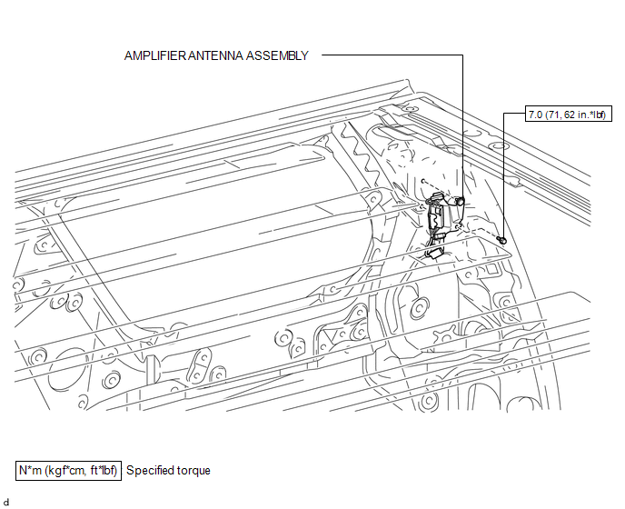
COMPONENTS
ILLUSTRATION
Removal
REMOVAL
PROCEDURE
1. REMOVE ROOF HEADLINING ASSEMBLY
(See page .gif) )
)
2. REMOVE AMPLIFIER ANTENNA ASSEMBLY
|
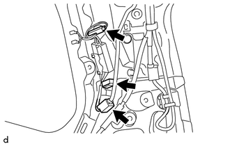
(a) Disconnect the 3 connectors. |
|
|
(b) Remove the clip. |
|
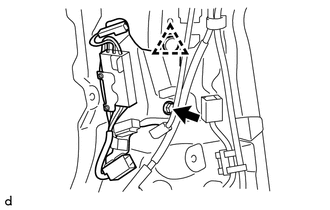
(c) Remove the bolt and amplifier antenna assembly.
Installation
INSTALLATION
PROCEDURE
1. INSTALL AMPLIFIER ANTENNA ASSEMBLY
(a) Install the amplifier antenna assembly with the bolt and clip.
Torque:
7.0 N·m {71 kgf·cm, 62 in·lbf}
(b) Connect the 3 connectors.
2. INSTALL ROOF HEADLINING ASSEMBLY
(See page .gif) )
)
 Audio / Video
...

Other materials about Toyota 4Runner:
Reassembly
REASSEMBLY
CAUTION / NOTICE / HINT
HINT:
Use the same procedure for both the RH and LH sides.
The procedure listed below is for the LH side.
PROCEDURE
1. INSTALL FRONT DOOR PANEL CUSHION
(a) Attach the claw to install a new f ...
Customize Parameters
CUSTOMIZE PARAMETERS
1. CUSTOMIZING FUNCTION WITH TECHSTREAM (REFERENCE)
NOTICE:
When the customer requests a change in a function, first make sure that
the function can be customized.
Record the current settings before customizing.
( ...

0.0251