Toyota 4Runner: Back Door Entry Lock Function does not Operate
DESCRIPTION
If the back door entry lock function does not operate but the back door unlock function operates, the communication line between the vehicle and electrical key transmitter is normal. The entry lock switch circuit (back door control switch → certification ECU) may be faulty.
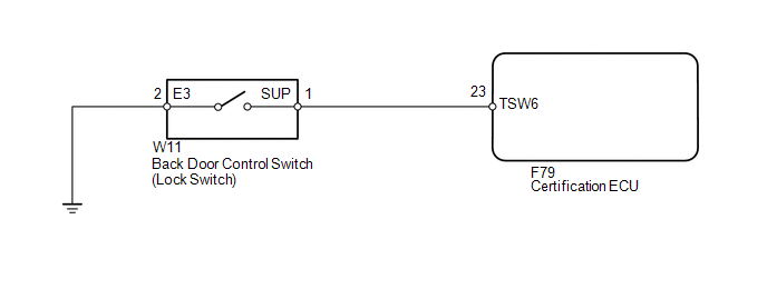
WIRING DIAGRAM
CAUTION / NOTICE / HINT
NOTICE:
- The smart key system (for Entry Function) uses a multiplex communication
system (LIN communication system) and the CAN communication system. Inspect
the communication function by following How to Proceed with Troubleshooting
(See page
.gif) ). Troubleshoot the smart key
). Troubleshoot the smart key
system (for Entry Function) after confirming that the communication systems are functioning properly. - When using the Techstream with the engine switch off to troubleshoot: Connect the Techstream to the DLC3 and turn a courtesy light switch on and off at 1.5-second intervals until communication between the Techstream and vehicle begins.
- Check that there are no electrical key transmitters in the vehicle.
- When checking the entry lock operation multiple times, the lock operation may be limited to 2 consecutive operations depending on the settings. In order to perform the entry lock operation 3 or more times, an unlock operation must be performed once (any type of unlock operation is sufficient). However, only consecutive entry lock operations are limited. Using the wireless lock or other types of lock operations, it is possible to perform consecutive lock operations without this limitation.
- Before replacing the certification ECU, refer to the engine immobiliser
system (w/ Smart Key System) (See page
).
PROCEDURE
|
1. |
CHECK POWER DOOR LOCK OPERATION |
(a) When the door control switch on the multiplex network master switch assembly
is operated, check that the doors unlock and lock according to the switch operation
(See page ).
OK:
Door locks operate normally.
| NG | .gif) |
GO TO POWER DOOR LOCK CONTROL SYSTEM |
|
.gif)
|
2. |
READ VALUE USING TECHSTREAM (LOCK SWITCH) |
(a) Using the Techstream, read the Data List (See page
).
Smart Key
|
Tester Display |
Measurement Item/Range |
Normal Condition |
Diagnostic Note |
|---|---|---|---|
|
Tr/B-Door Lock SW |
Back door lock switch / ON or OFF |
ON: Back door lock switch pushed OFF: Back door lock switch not pushed |
- |
OK:
"ON" (lock switch is pushed) and "OFF" (lock switch is not pushed) appear on the screen.
| OK | |
REPLACE CERTIFICATION ECU |
|
|
3. |
INSPECT BACK DOOR CONTROL SWITCH (LOCK SWITCH) |
(a) Remove the back door control switch (See page
).
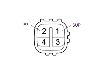
(b) Measure the resistance according to the value(s) in the table below.
Standard Resistance:
|
Tester Connection |
Switch Condition |
Specified Condition |
|---|---|---|
|
1 (SUP) - 2 (E3) |
No switch pushed |
10 kΩ or higher |
|
1 (SUP) - 2 (E3) |
Lock switch pushed |
Below 1 Ω |
| NG | |
REPLACE BACK DOOR CONTROL SWITCH |
|
|
4. |
CHECK HARNESS AND CONNECTOR (BACK DOOR CONTROL SWITCH - CERTIFICATION ECU) |
(a) Disconnect the W11 switch connector.
(b) Disconnect the F79 ECU connector.
(c) Measure the resistance according to the value(s) in the table below.
Standard Resistance:
|
Tester Connection |
Condition |
Specified Condition |
|---|---|---|
|
W11-1 (SUP) - F79-23 (TSW6) |
Always |
Below 1 Ω |
|
W11-2 (E3) - Body ground |
Always |
Below 1 Ω |
|
W11-1 (SUP) - Body ground |
Always |
10 kΩ or higher |
| OK | |
REPLACE CERTIFICATION ECU |
| NG | |
REPAIR OR REPLACE HARNESS OR CONNECTOR |
 Back Door Entry Lock and Unlock Functions do not Operate
DESCRIPTION
When the back door entry lock and unlock functions do not operate, one of the
following may be malfunctioning: 1) the power door lock control system, 2) the electrical
key antenna (ou ...

Other materials about Toyota 4Runner:
Installation
INSTALLATION
CAUTION / NOTICE / HINT
HINT:
A bolt without a torque specification is shown in the standard bolt chart (See
page ).
PROCEDURE
1. INSTALL POWER MANAGEMENT CONTROL ECU
(a) Attach the 2 claws to install the power management control ECU.
2. ...
Cruise control
Use the cruise control to maintain a set speed without depressing the
accelerator pedal.
1. Indicators
2. Cruise control switch
Setting the vehicle speed
Press the “ON-OFF” button to activate the cruise control.
Cruise control indicator will co ...

0.0234