Toyota 4Runner: Back Door Garnish(for Side)
Components
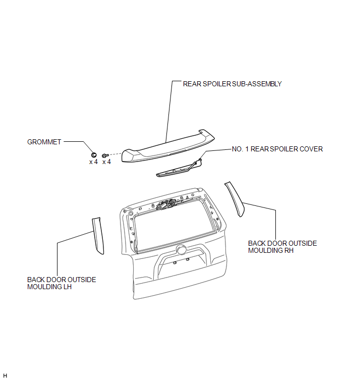
COMPONENTS
ILLUSTRATION
Installation
INSTALLATION
PROCEDURE
1. INSTALL BACK DOOR OUTSIDE MOULDING LH
(a) Attach the 5 clips to install the back door outside moulding.
2. INSTALL BACK DOOR OUTSIDE MOULDING RH
HINT:
Use the same procedure described for the LH side.
3. INSTALL REAR SPOILER SUB-ASSEMBLY
.gif)
4. INSTALL NO. 1 REAR SPOILER COVER
Removal
REMOVAL
PROCEDURE
1. REMOVE NO. 1 REAR SPOILER COVER
.gif)
2. REMOVE REAR SPOILER SUB-ASSEMBLY
3. REMOVE BACK DOOR OUTSIDE MOULDING LH
NOTICE:
- Do not remove the clips.
- If the clips are damaged or fall off, replace them with new clips.
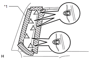
(a) Put protective tape around the back door outside moulding.
(b) Detach the 5 clips and remove the back door outside moulding.
Text in Illustration|
*1 |
Protective Tape |
4. REMOVE BACK DOOR OUTSIDE MOULDING RH
HINT:
Use the same procedure described for the LH side.
 Installation
INSTALLATION
PROCEDURE
1. INSTALL OUTER BACK DOOR GLASS WEATHERSTRIP ASSEMBLY
(a) Attach the 8 claws to install the outer back door glass weatherstrip.
2. INSTALL BACK DOOR GLASS
3. INSTALL BA ...

Other materials about Toyota 4Runner:
Using the AUX port
This port can be used to connect a portable audio device and listen to it
through the vehicle’s speakers.
Pull up the lid.
Open the cover and connect the portable audio device.
Press
or
.
Operating portable audio devices connected to the audio ...
Security Indicator Light Assembly
Components
COMPONENTS
ILLUSTRATION
Removal
REMOVAL
PROCEDURE
1. REMOVE NO. 2 INSTRUMENT CLUSTER FINISH PANEL GARNISH
2. REMOVE SECURITY INDICATOR LIGHT ASSEMBLY
(a) Pull the security indicator light assembly to detach the 4 claws
...

0.0089