Toyota 4Runner: Brake Signal Malfunction (B2284)
DESCRIPTION
This DTC is stored when the brake signal information from the cable and the brake signal information from the CAN communication line are inconsistent
HINT:
When the power management control ECU is replaced with a new one and the cable is connected to the negative (-) battery terminal, the power source mode is reset to on (IG). When the battery is removed and reinstalled, the power source mode that was selected when the battery was removed is restored.
|
DTC Code |
DTC Detection Condition |
Trouble Area |
|---|---|---|
|
B2284 |
The brake signal information from the cable and the brake signal information from the CAN communication line are inconsistent. |
|
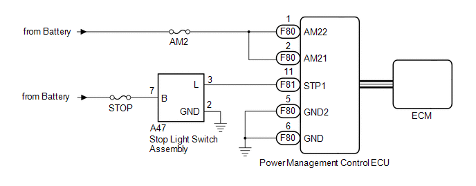
WIRING DIAGRAM
CAUTION / NOTICE / HINT
NOTICE:
- When using the Techstream with the engine switch off to troubleshoot: Connect the Techstream to the vehicle and turn a courtesy light switch on and off at 1.5 second intervals until communication between the Techstream and vehicle begins.
- Before performing the inspection, check that there are no problems related to the CAN communication system and LIN communication system.
- Inspect the fuses for circuits related to this system before performing the following inspection procedure.
HINT:
Check the connector connections and terminals to make sure that there are no abnormalities such as loose connections, deformation, etc.
PROCEDURE
|
1. |
CHECK HARNESS AND CONNECTOR (BATTERY - POWER MANAGEMENT CONTROL ECU) |
.gif)
| NG | .gif) |
REPAIR OR REPLACE HARNESS OR CONNECTOR |
|
.gif)
|
2. |
CHECK HARNESS AND CONNECTOR (POWER MANAGEMENT CONTROL ECU - BODY GROUND) |
| NG | |
REPAIR OR REPLACE HARNESS OR CONNECTOR |
|
|
3. |
INSPECT STOP LIGHT SWITCH ASSEMBLY |
(a) Inspect the stop light switch assembly (See page
).
| NG | |
REPLACE STOP LIGHT SWITCH ASSEMBLY |
|
|
4. |
CHECK HARNESS AND CONNECTOR (POWER MANAGEMENT CONTROL ECU - STOP LIGHT SWITCH ASSEMBLY) |
(a) Disconnect the F81 power management control ECU connector.
(b) Disconnect the A47 stop light switch assembly connector.
(c) Measure the resistance according to the value(s) in the table below.
Standard Resistance:
|
Tester Connection |
Condition |
Specified Condition |
|---|---|---|
|
F81-11 (STP1) - A47-3 (L) |
Always |
Below 1 Ω |
|
F81-11 (STP1) - Body ground |
Always |
10 kΩ or higher |
|
(d) Reconnect the A47 stop light switch assembly connector. |
|
(e) Measure the voltage according to the value(s) in the table below.
Standard Voltage:
|
Tester Connection |
Condition |
Specified Condition |
|---|---|---|
|
F81-11 (STP1) - Body ground |
Brake pedal not depressed |
Below 1 V |
|
Brake pedal depressed |
([Voltage at terminal AM21 or AM22] minus 2.0 V) or higher |
|
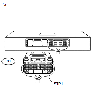
*a |
Rear view of wire harness connector (to Power Management Control ECU) |
| NG | |
REPAIR OR REPLACE HARNESS OR CONNECTOR |
|
|
5. |
READ VALUE USING TECHSTREAM (STOP LIGHT SWITCH) |
(a) Connect the Techstream to the DLC3.
(b) Turn the engine switch on (IG).
(c) Turn the Techstream on.
(d) Enter the following menus: Body Electrical / Power Source Control / Data List.
(e) According to the display on the Techstream, read the Data List.
Power Source Control|
Tester Display |
Measurement Item/Range |
Normal Condition |
Diagnostic Note |
|---|---|---|---|
|
Stop Light Switch1 |
Stop light switch 1 / ON or OFF |
ON: Brake pedal depressed OFF: Brake pedal released |
- |
OK:
ON (brake pedal depressed) or OFF (brake pedal released) appears on the screen according to the stop light switch condition.
| OK | |
REPLACE POWER MANAGEMENT CONTROL ECU |
| NG | |
GO TO SFI SYSTEM (HOW TO PROCEED WITH TROUBLESHOOTING) |
 Ignition Hold Monitor Malfunction (B2271)
DESCRIPTION
This DTC is stored when a problem, such as an open in the AM2 fuse, an open or
short in the wire harness between the fuse and power management control ECU, a short
in the IG output ci ...
 Engine does not Start
DESCRIPTION
The push-button start function uses a push-type engine switch, which the driver
can operate by merely carrying the key. This system consists primarily of the power
management control ...
Other materials about Toyota 4Runner:
TC and CG Terminal Circuit
DESCRIPTION
DTC output mode is set by connecting terminals 13 (TC) and 4 (CG) of the DLC3.
The DTCs are output by the blinking of the tire pressure warning light.
WIRING DIAGRAM
HINT:
When each warning light blinks continuously, a ground short in the w ...
Invalid Data Received from Deceleration Sensor (C1442,C1443)
DESCRIPTION
The skid control ECU receives signals from the yaw rate and acceleration sensor
via the CAN communication system.
DTC Code
DTC Detection Condition
Trouble Area
C1442
An invalid data s ...

0.0088