Toyota 4Runner: Center Airbag Sensor Assembly
Components
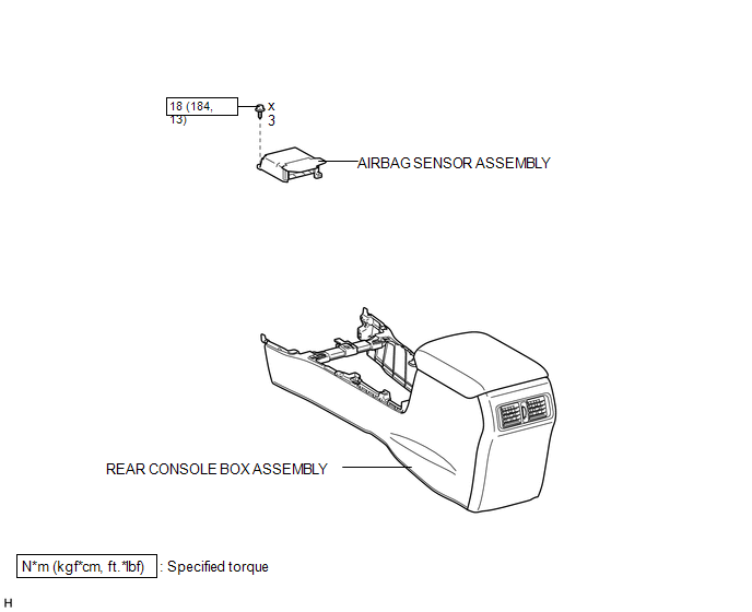
COMPONENTS
ILLUSTRATION
On-vehicle Inspection
ON-VEHICLE INSPECTION
PROCEDURE
1. CHECK AIRBAG SENSOR ASSEMBLY (VEHICLE NOT INVOLVED IN COLLISION)
(a) Perform a diagnostic system check (See page
.gif) ).
).
2. CHECK AIRBAG SENSOR ASSEMBLY (VEHICLE INVOLVED IN COLLISION AND AIRBAG HAS NOT DEPLOYED)
(a) Perform a diagnostic system check (See page
).
3. CHECK AIRBAG SENSOR ASSEMBLY (VEHICLE INVOLVED IN COLLISION AND AIRBAG HAS DEPLOYED)
(a) Replace the airbag sensor.
CAUTION:
For removal and installation of the airbag sensor, be sure to follow the correct procedure.
HINT:
The airbag sensor should be replaced after any of the airbags has deployed, as it has been subjected to an impact.
Installation
INSTALLATION
PROCEDURE
1. INSTALL AIRBAG SENSOR ASSEMBLY
(a) Turn the ignition switch off.
(b) Disconnect the cable from the negative (-) battery terminal.
CAUTION:
Wait at least 90 seconds after disconnecting the cable from the negative (-) battery terminal to disable the SRS system.
NOTICE:
When disconnecting the cable, some systems need to be initialized after the cable
is reconnected (See page .gif) ).
).
(c) Install the airbag sensor with the 3 bolts.
Torque:
18 N·m {184 kgf·cm, 13 ft·lbf}
NOTICE:
- If the airbag sensor has been dropped, or there are any cracks, dents or other defects in the case, bracket or connector, replace it with a new one.
- When installing the airbag sensor, be careful that the SRS wiring does not interfere with other parts and that it is not pinched between other parts.
(d) Check that the airbag sensor is not loose.
(e) Connect the connector.
2. INSTALL REAR CONSOLE BOX ASSEMBLY
(a) Install the rear console box assembly (See page
).
3. CONNECT CABLE TO NEGATIVE BATTERY TERMINAL
NOTICE:
When disconnecting the cable, some systems need to be initialized after the cable
is reconnected (See page ).
4. CHECK SRS WARNING LIGHT
(a) Check the SRS warning light (See page ).
Removal
REMOVAL
PROCEDURE
1. DISCONNECT CABLE FROM NEGATIVE BATTERY TERMINAL
CAUTION:
Wait at least 90 seconds after disconnecting the cable from the negative (-) battery terminal to disable the SRS system.
NOTICE:
When disconnecting the cable, some systems need to be initialized after the cable
is reconnected (See page .gif) ).
).
2. REMOVE REAR CONSOLE BOX ASSEMBLY
(a) Remove the rear console box sub-assembly (See page
).
3. REMOVE AIRBAG SENSOR ASSEMBLY
|
(a) Disconnect the connector. |
|
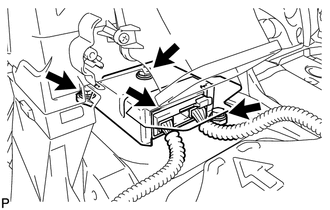
(b) Remove the 3 bolts and airbag sensor.
 Diagnosis Circuit
DESCRIPTION
DTC output mode is set by connecting terminals TC and CG of the DLC3.
DTCs are output by the blinking of the SRS warning light.
HINT:
When each warning light continues blinking ...

Other materials about Toyota 4Runner:
Confirm Vehicle Headunit Functionality
PROCEDURE
1.
CHECK CUSTOMER'S CELLULAR PHONE COMPATIBILITY
(a) Go to TIS "Bluetooth" Compatibility Portal and check if the cellular phone
is compatible.
Result
Proceed to
...
VFC Solenoid Circuit (C15F0)
DESCRIPTION
This circuit supplies electric power to the power steering solenoid valve.
The power steering ECU assembly controls the output current to the power steering
solenoid valve in accordance with the steering angle signal, steering zero point
memo ...

0.0262