Toyota 4Runner: Dcm Power Source Circuit
DESCRIPTION
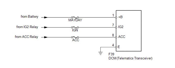
This is the power source circuit to operate the DCM (Telematics Transceiver).
WIRING DIAGRAM
CAUTION / NOTICE / HINT
NOTICE:
Inspect the fuses for circuits related to this system before performing the following inspection procedure.
PROCEDURE
|
1. |
CHECK HARNESS AND CONNECTOR (DCM - BATTERY AND BODY GROUND) |
|
(a) Disconnect the F39 DCM (Telematics Transceiver) connector. |
|
(b) Measure the resistance according to the value(s) in the table below.
Standard Resistance:
|
Tester Connection |
Condition |
Specified Condition |
|---|---|---|
|
F39-4 (E) - Body ground |
Always |
Below 1 Ω |
(c) Measure the voltage according to the value(s) in the table below
Standard Voltage:
|
Tester Connection |
Switch Condition |
Specified Condition |
|---|---|---|
|
F39-1 (+B) - F39-4 (E) |
Always |
11 to 14 V |
|
F39-7 (IG2) - F39-4 (E) |
Ignition switch ON |
11 to 14 V |
|
F39-8 (ACC) - F39-4 (E) |
Ignition switch ACC |
11 to 14 V |
|
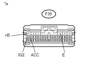
*a |
Front view of wire harness connector (to DCM [Telematics Transceiver]) |
| OK | .gif) |
PROCEED TO NEXT SUSPECTED AREA SHOWN IN PROBLEM SYMPTOMS TABLE |
| NG | |
REPAIR OR REPLACE HARNESS OR CONNECTOR |
 GPS Signal Unreceived (B1583)
DESCRIPTION
If GPS satellite signals cannot be acquired for 24 consecutive kilometers (15
consecutive miles), this DTC is set.
DTC Code
DTC Detection Condition
Tro ...
 Green And Red Indicators Blink Simultaneously
DESCRIPTION
After the ignition switch is turned to ON, the DCM (Telematics Transceiver) will
enter a self check mode. The manual (SOS) switch red indicator will illuminate for
2 seconds and turn ...
Other materials about Toyota 4Runner:
Automatic transmission
Select a shift position appropriate for the driving conditions.
Shifting the shift lever
Vehicles without a smart key
system:
While the engine switch is in the “ON” position, move the shift lever with
the brake pedal depressed.
Vehicles with a s ...
Data List / Active Test
DATA LIST / ACTIVE TEST
1. READ DATA LIST
HINT:
Using the Techstream to read the Data List allows the values or states of switches,
sensors, actuators and other items to be read without removing any parts. This non-intrusive
inspection can be very usefu ...

0.0117