Toyota 4Runner: Disassembly
DISASSEMBLY
PROCEDURE
1. REMOVE FRONT NO. 1 LOWER ARM BUSH LH
|
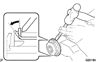
(a) Using a chisel and hammer, pry the flange of the bush outward. |
|
|
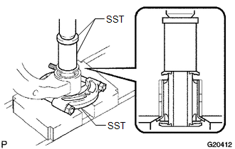
(b) Using SST and a press, press out the bush. SST: 09632-36010 SST: 09950-00020 SST: 09950-60010 09951-00400 |
|
2. REMOVE FRONT NO. 2 LOWER ARM BUSH LH
|
(a) Using a chisel and hammer, pry the flange of the bush outward. |
|
|
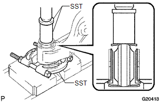
(b) Using SST and a press, press out the bush. SST: 09632-36010 SST: 09950-00020 SST: 09950-60010 09951-00400 |
|
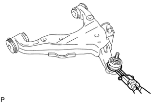
3. REMOVE LOWER BALL JOINT DUST COVER LH
|
(a) Using a snap ring expander, remove the dust cover set ring and dust cover from the lower arm. NOTICE:
|
|
 Removal
REMOVAL
CAUTION / NOTICE / HINT
HINT:
Use the same procedure for the RH and LH sides.
The procedure listed below is for the LH side.
PROCEDURE
1. REMOVE FRONT WHEEL
2. REMOVE L ...
 Inspection
INSPECTION
PROCEDURE
1. INSPECT FRONT NO. 1 SUSPENSION LOWER ARM SUB-ASSEMBLY LH
(a) As shown in the illustration, flip the ball joint stud back and forth
5 times before installing t ...
Other materials about Toyota 4Runner:
Adjustment
ADJUSTMENT
PROCEDURE
1. STEERING OFF CENTER ADJUSTMENT PROCEDURE
HINT:
This is the adjustment procedure for when the steering is off center.
(a) Check if the steering wheel is off center.
(1) Apply masking tape to the top center of the steerin ...
Removal
REMOVAL
PROCEDURE
1. DISCONNECT CABLE FROM NEGATIVE BATTERY TERMINAL
CAUTION:
Wait at least 90 seconds after disconnecting the cable from the negative (-)
battery terminal to disable the SRS system.
NOTICE:
When disconnecting the cable, some systems ne ...

0.029