Toyota 4Runner: Disassembly
DISASSEMBLY
PROCEDURE
1. REMOVE BLOWER ASSEMBLY
|
(a) Remove the bolt. |
|
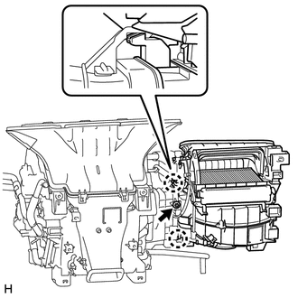
(b) Detach the 2 claws and remove the blower unit assembly.
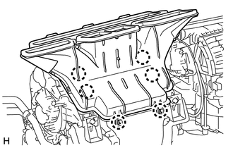
2. REMOVE DEFROSTER NOZZLE ASSEMBLY
|
(a) Detach the 6 claws and remove the defroster nozzle assembly. |
|
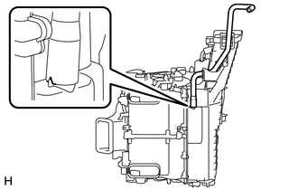
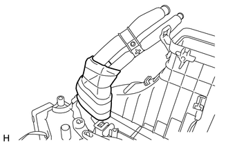
3. REMOVE ASPIRATOR HOSE
|
(a) Detach the 2 claws and remove the aspirator hose. |
|
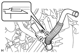
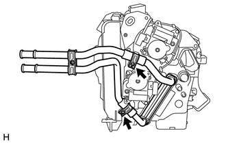
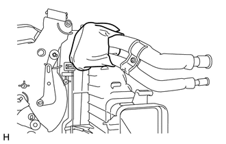
4. REMOVE DRAIN COOLER HOSE
|
(a) Remove the drain cooler hose. |
|
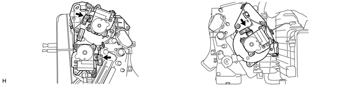
5. REMOVE QUICK HEATER ASSEMBLY (w/ PTC Heater)
.gif)
6. REMOVE HEATER RADIATOR UNIT SUB-ASSEMBLY
(a) Remove the 2 screws and 2 radiator brackets.
(b) Remove the radiator.
7. REMOVE AIR CONDITIONING HARNESS
(a) Disconnect the connectors.
(b) Detach the clamps and remove the harness.
8. REMOVE AIR CONDITIONING TUBE AND ACCESSORY ASSEMBLY
|
(a) Remove the packing. |
|
|
(b) Remove the butyl tape. |
|
|
(c) Using a 4 mm hexagon wrench, remove the 2 hexagon bolts and the air conditioner tube and accessory assembly. |
|
(d) Remove the 2 O-rings from the air conditioning tube and accessory assembly.
9. REMOVE COOLER EXPANSION VALVE
|
(a) Remove the cooler expansion valve. |
|
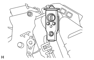
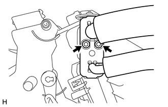
10. REMOVE DAMPER SERVO SUB-ASSEMBLY LH
|
(a) Remove the 4 screws and damper servo sub-assembly LH. |
|
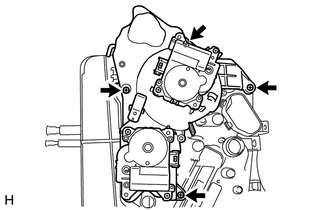
11. REMOVE DAMPER SERVO SUB-ASSEMBLY RH
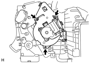
(a) Remove the 3 screws and damper servo sub-assembly RH.
12. REMOVE NO. 1 COOLER EVAPORATOR SUB-ASSEMBLY
|
(a) Remove the 6 screws. |
|
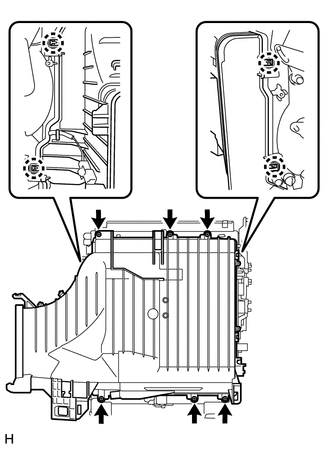
(b) Detach the 4 claws and remove the unit case.
|
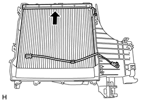
(c) Remove the evaporator. |
|
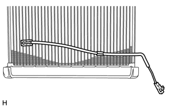
(d) Remove the 2 O-rings from the evaporator.
13. REMOVE NO. 1 COOLER THERMISTOR
|
(a) Remove the thermistor. |
|
 Components
COMPONENTS
ILLUSTRATION
ILLUSTRATION
ILLUSTRATION
ILLUSTRATION
...
 Removal
REMOVAL
PROCEDURE
1. DRAIN ENGINE COOLANT
(a) Drain engine coolant (See page ).
2. RECOVER REFRIGERANT FROM REFRIGERATION SYSTEM
3. DISCONNECT CABLE FROM NEGATIVE BATTERY TERMINAL
CAUTION:
...
Other materials about Toyota 4Runner:
GPS Antenna Connection Malfunction(short) (B15C0,B15C1)
DESCRIPTION
These DTCs are stored when a malfunction occurs in the navigation antenna assembly.
DTC No.
DTC Detection Condition
Trouble Area
B15C0
Navigation antenna error
Nav ...
System Description
SYSTEM DESCRIPTION
1. FRONT POWER SEAT CONTROL SYSTEM DESCRIPTION
The driver seat is equipped with slide, reclining, lifter, front vertical
and lumbar support adjustment functions.
The passenger seat is equipped with slide and reclining adjust ...

0.0266