Toyota 4Runner: Disassembly
DISASSEMBLY
PROCEDURE
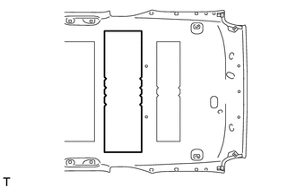
1. REMOVE NO. 1 ROOF SILENCER PAD (w/o Sliding Roof)
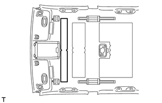
(a) Remove the No. 1 roof silencer pad.
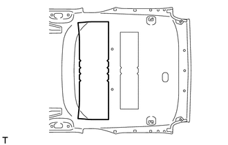
2. REMOVE NO. 2 ROOF SILENCER PAD
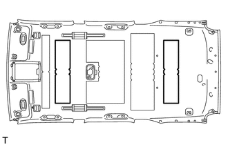
(a) w/o Sliding Roof:
Remove the 2 No. 2 roof silencer pads.
|
(b) w/ Sliding Roof: Remove the No. 2 roof silencer pad. |
|
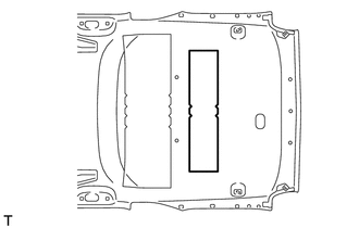
3. REMOVE NO. 3 ROOF SILENCER PAD (w/o Sliding Roof)
(a) Remove the No. 3 roof silencer pad.
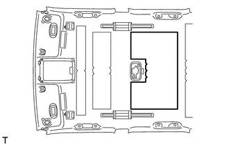
4. REMOVE NO. 4 ROOF SILENCER PAD
(a) w/o Sliding Roof:
Remove the No. 4 roof silencer pad.
|
(b) w/ Sliding Roof: Remove the No. 4 roof silencer pad. |
|
5. REMOVE VANITY LIGHT ASSEMBLY
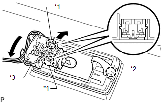
HINT:
Use the same procedure for the other vanity light.
(a) Detach the 2 claws labeled A and separate the bulb holder from the vanity light as shown in the illustration.
(b) Detach the claw labeled B and remove the vanity light.
Text in Illustration|
*1 |
Claw A |
|
*2 |
Claw B |
|
*3 |
Bulb Holder |
6. REMOVE NO. 1 ROOF WIRE
(a) Turn the visor connectors approximately 90° clockwise and remove them from the roof headlining.
(b) Detach each clamp and remove the tape and No. 1 roof wire.
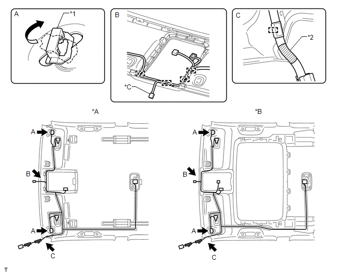 Text in Illustration
|
*A |
w/o Sliding Roof |
*B |
w/ Sliding Roof |
|
*C |
w/ EC Mirror |
- |
- |
|
*1 |
Visor Connector |
*2 |
Marking Tape |
7. REMOVE NO. 2 ANTENNA CORD SUB-ASSEMBLY
(a) w/o Sliding Roof:
Remove the No. 2 antenna cord sub-assembly (See page
.gif) ).
).
(b) w/ Sliding Roof:
Remove the No. 2 antenna cord sub-assembly (See page
).
 Components
COMPONENTS
ILLUSTRATION
ILLUSTRATION
ILLUSTRATION
ILLUSTRATION
ILLUSTRATION
ILLUSTRATION
ILLUSTRATION
ILLUSTRATION
ILLUSTRATION
ILLUSTRATION
ILLUSTRATION
ILLUSTRATION ...
 Reassembly
REASSEMBLY
PROCEDURE
1. INSTALL NO. 2 ANTENNA CORD SUB-ASSEMBLY
(a) w/o Sliding Roof:
Install the No. 2 antenna cord sub-assembly (See page
).
(b) w/ Sliding Roof:
Install the No. 2 antenna co ...
Other materials about Toyota 4Runner:
System Description
SYSTEM DESCRIPTION
1. LIN COMMUNICATION SYSTEM DESCRIPTION
The LIN communication system is used for communication between the components
in the tables below. If communication cannot be performed through LIN communication
because of a break in the communi ...
Vehicle Control History
VEHICLE CONTROL HISTORY
1. Function Overview
(a) The vehicle control history is a function that records control data (record
data) when triggered by specific vehicle behavior. When DTCs are not detected according
to information provided by customers, by ...

0.0257