Toyota 4Runner: Disassembly
DISASSEMBLY
PROCEDURE
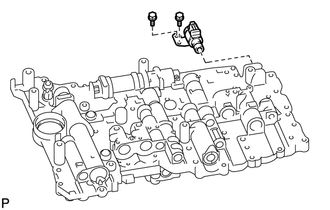
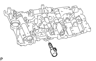
1. REMOVE SHIFT SOLENOID VALVE SR
|
(a) Remove the 2 bolts and solenoid valve. |
|
2. REMOVE SHIFT SOLENOID VALVE SLU
|
(a) Remove the bolt, solenoid lock plate and 2 straight pins. |
|
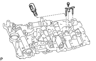
(b) Remove the solenoid valve.
3. REMOVE SHIFT SOLENOID VALVE SL2
4. REMOVE SHIFT SOLENOID VALVE SLT
|
(a) Remove the bolt, solenoid lock plate and 2 straight pins. |
|
(b) Remove the solenoid valve.
5. REMOVE SHIFT SOLENOID VALVE SL1
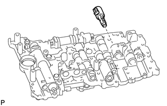
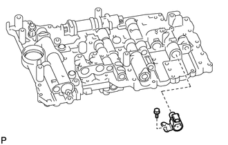
6. REMOVE SHIFT SOLENOID VALVE S1
|
(a) Remove the bolt and shift solenoid valve. |
|
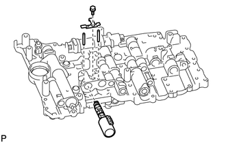
7. REMOVE SHIFT SOLENOID VALVE S2
|
(a) Remove the bolt and solenoid valve. |
|
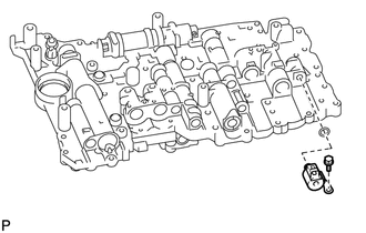
(b) Remove the O-ring from the shift solenoid valve.
 Removal
REMOVAL
PROCEDURE
1. DRAIN AUTOMATIC TRANSMISSION FLUID
2. REMOVE AUTOMATIC TRANSMISSION OIL PAN SUB-ASSEMBLY
3. REMOVE VALVE BODY OIL STRAINER ASSEMBLY
4. DISCONNECT TRANSMISSION WIRE
...
 Inspection
INSPECTION
PROCEDURE
1. INSPECT SHIFT SOLENOID VALVE SR
(a) Measure the resistance according to the value(s) in the table below.
Standard Resistance:
Tester Connection
Co ...
Other materials about Toyota 4Runner:
Installation
INSTALLATION
CAUTION / NOTICE / HINT
HINT:
A bolt without a torque specification is shown in the standard bolt chart (See
page ).
PROCEDURE
1. INSTALL SIDE AUTO STEP CONTROLLER ECU ASSEMBLY
(a) Engage the guide and install the side auto step controlle ...
Removal
REMOVAL
CAUTION / NOTICE / HINT
HINT:
Use the same procedure for the RH and LH sides.
The procedure listed below is for the LH side.
PROCEDURE
1. REMOVE FRONT WHEEL
2. REMOVE DISC BRAKE CYLINDER ASSEMBLY LH
3. REMOVE FRONT DISC
...

0.008