Toyota 4Runner: Inspection
INSPECTION
PROCEDURE
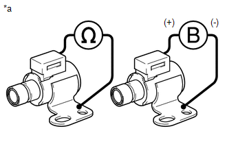
1. INSPECT SHIFT SOLENOID VALVE SR
.png)
(a) Measure the resistance according to the value(s) in the table below.
Standard Resistance:
|
Tester Connection |
Condition |
Specified Condition |
|---|---|---|
|
Shift solenoid valve SR connector terminal - Shift solenoid valve SR body |
20°C (68°F) |
11 to 15 Ω |
|
*a |
Component without harness connected (Shift Solenoid Valve SR) |
(b) Apply 12 V battery voltage to the shift solenoid valve and check that the valve moves and makes an operating noise.
OK:
|
Measurement Condition |
Specified Condition |
|---|---|
|
Valve moves and makes an operating noise |
If the result is not as specified, replace the solenoid valve.
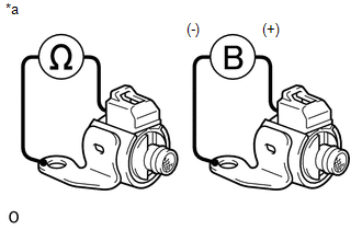
2. INSPECT SHIFT SOLENOID VALVE SL1 AND SL2
.png)
(a) Measure the resistance according to the value(s) in the table below.
Standard Resistance:
|
Tester Connection |
Condition |
Specified Condition |
|---|---|---|
|
1 - 2 |
20°C (68°F) |
5.0 to 5.6 Ω |
|
*a |
Component without harness connected (Shift Solenoid Valve) |
(b) Apply 12 V battery voltage to the shift solenoid valve and check that the valve moves and makes an operating noise.
OK:
|
Measurement Condition |
Specified Condition |
|---|---|
|
Valve moves and makes an operating noise |
If the result is not as specified, replace the solenoid valve.
3. INSPECT SHIFT SOLENOID VALVE SLT AND SLU
.png)
(a) Measure the resistance according to the value(s) in the table below.
Standard Resistance:
|
Tester Connection |
Condition |
Specified Condition |
|---|---|---|
|
1 -2 |
20°C (68°F) |
5.0 to 5.6 Ω |
|
*a |
Component without harness connected (Shift Solenoid Valve) |
(b) Apply 12 V battery voltage to the shift solenoid valve and check that the valve moves and makes an operating noise.
OK:
|
Measurement Condition |
Specified Condition |
|---|---|
|
Battery positive (+) with a 21 W bulb → Terminal 2 Battery negative (-) → Terminal 1 |
Valve moves and makes an operating noise |
If the result is not as specified, replace the solenoid valve.
4. INSPECT SHIFT SOLENOID VALVE S1
(a) Measure the resistance according to the value(s) in the table below.
Standard Resistance:
|
Tester Connection |
Condition |
Specified Condition |
|---|---|---|
|
Shift solenoid valve S1 connector terminal - Shift solenoid valve S1 body |
20°C (68°F) |
11 to 15 Ω |
|
*a |
Component without harness connected (Shift Solenoid Valve S1) |
(b) Apply 12 V battery voltage to the shift solenoid valve and check that the valve moves and makes an operating noise.
OK:
|
Measurement Condition |
Specified Condition |
|---|---|
|
Valve moves and makes an operating noise |
If the result is not as specified, replace the solenoid valve.
5. INSPECT SHIFT SOLENOID VALVE S2
(a) Measure the resistance according to the value(s) in the table below.
Standard Resistance:
|
Tester Connection |
Condition |
Specified Condition |
|---|---|---|
|
Shift solenoid valve S2 connector terminal - Shift solenoid valve S2 body |
20°C (68°F) |
11 to 15 Ω |
|
*a |
Component without harness connected (Shift Solenoid Valve S2) |
(b) Apply 12 V battery voltage to the shift solenoid valve and check that the valve moves and makes an operating noise.
OK:
|
Measurement Condition |
Specified Condition |
|---|---|
|
Valve moves and makes an operating noise |
If the result is not as specified, replace the solenoid valve.
 Disassembly
DISASSEMBLY
PROCEDURE
1. REMOVE SHIFT SOLENOID VALVE SR
(a) Remove the 2 bolts and solenoid valve.
2. REMOVE SHIFT SOLENOID VALVE SLU
...
 Installation
INSTALLATION
PROCEDURE
1. INSTALL TRANSMISSION VALVE BODY ASSEMBLY
(a) Install the spring and check ball body.
(b) Insert the pin of the manual valve into the hole of the manual valve
...
Other materials about Toyota 4Runner:
Installation
INSTALLATION
CAUTION / NOTICE / HINT
CAUTION:
Wear protective gloves. Sharp areas on the parts may injure your hands.
PROCEDURE
1. INSTALL REAR SEAT ASSEMBLY RH
(a) Place the seat in the cabin.
NOTICE:
Be careful not to damage the vehicle body.
HINT ...
IG2 Signal Malfunction (B2788)
DESCRIPTION
The steering lock ECU determines the on/off status of the engine switch through
the IG2 signal circuit.
The steering lock ECU does not lock the steering when it receives the IG2 relay
on signal. This prevents the steering from being locked wh ...

0.0259