Toyota 4Runner: Display Signal Circuit between Navigation Receiver Assembly and Television Camera Assembly
DESCRIPTION
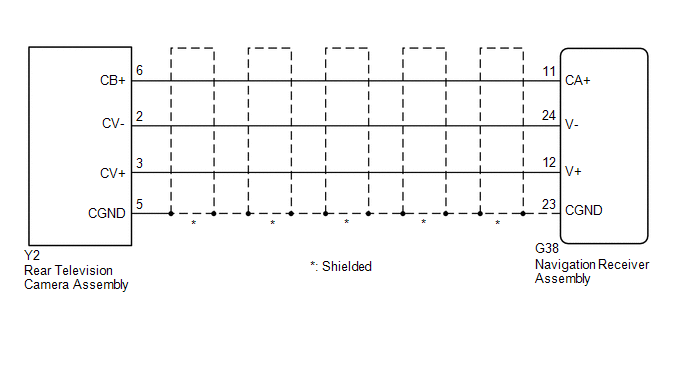
This is the display signal circuit between the navigation receiver assembly and the television camera assembly.
WIRING DIAGRAM
PROCEDURE
|
1. |
CHECK HARNESS AND CONNECTOR (NAVIGATION RECEIVER ASSEMBLY - REAR TELEVISION CAMERA ASSEMBLY) |
(a) Disconnect the G38 navigation receiver assembly connector.
(b) Disconnect the Y2 rear television camera assembly connector.
(c) Measure the resistance according to the value(s) in the table below.
Standard Resistance:
|
Tester Connection |
Condition |
Specified Condition |
|---|---|---|
|
G38-11 (CA+) - Y2-6 (CB+) |
Always |
Below 1 Ω |
|
G38-12 (V+) - Y2-3 (CV+) |
Always |
Below 1 Ω |
|
G38-23 (CGND) - Y2-5 (CGND) |
Always |
Below 1 Ω |
|
G38-24 (V-) - Y2-2 (CV-) |
Always |
Below 1 Ω |
|
G38-11 (CA+) - Body ground |
Always |
10 kΩ or higher |
|
G38-12 (V+) - Body ground |
Always |
10 kΩ or higher |
|
G38-23 (CGND) - Body ground |
Always |
10 kΩ or higher |
|
G38-24 (V-) - Body ground |
Always |
10 kΩ or higher |
| NG | .gif) |
REPAIR OR REPLACE HARNESS OR CONNECTOR |
|
.gif)
|
2. |
CHECK NAVIGATION RECEIVER ASSEMBLY |
(a) Reconnect the G38 navigation receiver assembly connector.
(b) Measure the resistance according to the value(s) in the table below.
Standard Resistance:
|
Tester Connection |
Condition |
Specified Condition |
|---|---|---|
|
G38-23 (CGND) - Body ground |
Always |
Below 1 Ω |
|
G38-24 (V-) - Body ground |
Always |
Below 1 Ω |
(c) Measure the voltage according to the value(s) in the table below.
Standard Voltage:
|
Tester Connection |
Condition |
Specified Condition |
|---|---|---|
|
G38-11 (CA+) - G38-23 (CGND) |
Ignition switch ACC |
5.5 to 7.05 V |
|
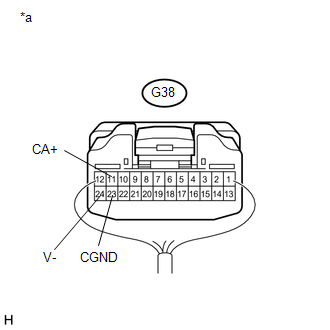
*a |
Component with harness connected (Navigation Receiver Assembly) |
| NG | |
PROCEED TO NEXT SUSPECTED AREA SHOWN IN PROBLEM SYMPTOMS TABLE |
|
|
3. |
CHECK REAR TELEVISION CAMERA ASSEMBLY |
(a) Reconnect the Y2 rear television camera assembly connector.
(b) Check the waveform of the rear television camera assembly using an oscilloscope.
HINT:
A waterproof connector is used for the rear television camera assembly. Therefore, inspect the waveform at the navigation receiver assembly with the connector connected.
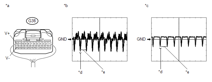 Text in Illustration
|
*a |
Component with harness connected (Navigation Receiver Assembly) |
*b |
Waveform 1 (under normal conditions) |
|
*c |
Waveform 2 (camera lens is covered, blacking out the screen) |
*d |
Synchronized Signal |
|
*e |
Video Waveform |
- |
- |
OK:
Waveform is as shown in the illustration.
|
Item |
Content |
|---|---|
|
Terminal No. (Symbol) |
G38-12 (V+) - G38-24 (V-) |
|
Tool Setting |
200 mV/DIV., 50 μsec./DIV. |
|
Condition |
Ignition switch ON, shift lever in R |
HINT:
The video waveform changes according to the image sent by the rear television camera assembly.
| OK | |
PROCEED TO NEXT SUSPECTED AREA SHOWN IN PROBLEM SYMPTOMS TABLE |
| NG | |
REPLACE REAR TELEVISION CAMERA ASSEMBLY |
 Back Camera Disconnected (C1622)
DESCRIPTION
This DTC is stored if the navigation receiver assembly judges that the signals
or signal lines between the navigation receiver assembly, and the rear television
camera assembly are no ...

Other materials about Toyota 4Runner:
Data List / Active Test
DATA LIST / ACTIVE TEST
1. READ DATA LIST
HINT:
Using the Techstream to read the Data List allows values or states of switches,
sensors, actuators and other items to be read without removing any parts. This non-intrusive
inspection can be very useful be ...
Removal
REMOVAL
CAUTION / NOTICE / HINT
CAUTION:
Wear protective gloves. Sharp areas on the parts may injure your hands.
HINT:
Use the same procedure for the RH and LH sides.
The procedure listed below is for the LH side.
PROCEDURE
1. REMOVE D ...

0.0092