Toyota 4Runner: Front Brake Flexible Hose
Components
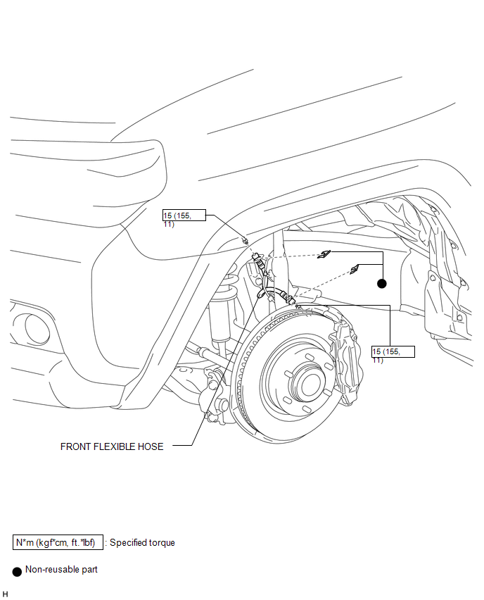
COMPONENTS
ILLUSTRATION
Removal
REMOVAL
CAUTION / NOTICE / HINT
HINT:
- Use the same procedure for the RH and LH sides.
- The procedure listed below is for the LH side.
PROCEDURE
1. REMOVE FRONT WHEEL
2. DRAIN BRAKE FLUID
NOTICE:
Wash off brake fluid immediately if it comes in contact with any painted surface.
3. REMOVE FRONT FLEXIBLE HOSE
|
(a) Remove the 2 clips. |
|
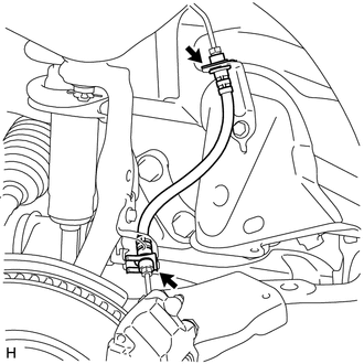
(b) Disconnect the brake tube from the front flexible hose with a union nut wrench while holding the front flexible hose with a wrench and remove the front flexible hose.
NOTICE:
- Do not bend or damage the brake tube.
- Do not allow any foreign matter such as dirt and dust to enter the brake tube from the connecting point.
Installation
INSTALLATION
CAUTION / NOTICE / HINT
HINT:
- Use the same procedure for the RH and LH sides.
- The procedure listed below is for the LH side.
PROCEDURE
1. INSTALL FRONT FLEXIBLE HOSE
(a) Using a union nut wrench, connect the brake tube to the front flexible hose while holding the front flexible hose with a wrench to install the front flexible hose.
Torque:
15 N·m {155 kgf·cm, 11 ft·lbf}
NOTICE:
- Do not bend or damage the brake tube.
- Do not allow any foreign matter such as dirt and dust to enter the brake tube from the connecting point.
- Use the formula to calculate special torque values for situations where
a union nut wrench is combined with a torque wrench (See page
.gif) ).
).
(b) Install 2 new clips to the front flexible hose.
2. BLEED BRAKE LINE
3. INSTALL FRONT WHEEL
 Installation
INSTALLATION
CAUTION / NOTICE / HINT
HINT:
Use the same procedure for the RH and LH sides.
The procedure listed below is for the LH side.
PROCEDURE
1. INSTALL FRONT DISC
(a) Al ...
 Brake (rear)
...
Other materials about Toyota 4Runner:
Problem Symptoms Table
PROBLEM SYMPTOMS TABLE
HINT:
Use the table below to help determine the cause of problem symptoms.
If multiple suspected areas are listed, the potential causes of the symptoms
are listed in order of probability in the "Suspected Area" ...
Installation
INSTALLATION
PROCEDURE
1. INSTALL NO. 2 PARKING BRAKE CABLE ASSEMBLY
(a) Attach the claws of the No. 2 parking brake cable.
(b) Install the No. 2 parking brake cable assembly to the parking brake equalizer
with the clip.
(c) Install the No. 2 parking br ...

0.0093