Toyota 4Runner: Personal Light(for Front Door)
Components
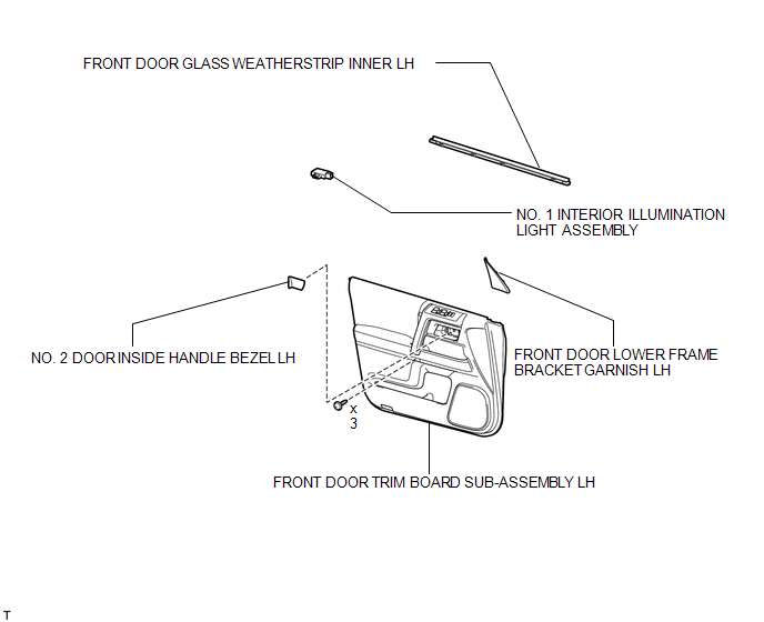
COMPONENTS
ILLUSTRATION
Inspection
INSPECTION
PROCEDURE
1. INSPECT NO. 1 INTERIOR ILLUMINATION LIGHT ASSEMBLY
|
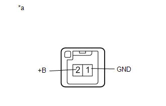
(a) Apply battery voltage to the connector and check the LED illumination. OK:
If the result is not as specified, replace the No. 1 interior illumination light assembly. Text in Illustration
|
|
Installation
INSTALLATION
CAUTION / NOTICE / HINT
HINT:
- Use the same procedure for the RH and LH sides.
- The procedure listed below is for the LH side.
PROCEDURE
1. INSTALL NO. 1 INTERIOR ILLUMINATION LIGHT ASSEMBLY
|
(a) Connect the connector. |
|
(b) Attach the claw to install the light.
2. INSTALL FRONT DOOR GLASS WEATHERSTRIP INNER LH
.gif)
3. INSTALL FRONT DOOR TRIM BOARD SUB-ASSEMBLY LH
4. INSTALL NO. 2 DOOR INSIDE HANDLE BEZEL LH
5. INSTALL FRONT DOOR LOWER FRAME BRACKET GARNISH LH
Removal
REMOVAL
CAUTION / NOTICE / HINT
HINT:
- Use the same procedure for the RH and LH sides.
- The procedure listed below is for the LH side.
PROCEDURE
1. REMOVE FRONT DOOR LOWER FRAME BRACKET GARNISH LH
.gif)
2. REMOVE NO. 2 DOOR INSIDE HANDLE BEZEL LH
3. REMOVE FRONT DOOR TRIM BOARD SUB-ASSEMBLY LH
4. REMOVE FRONT DOOR GLASS WEATHERSTRIP INNER LH
5. REMOVE NO. 1 INTERIOR ILLUMINATION LIGHT ASSEMBLY
|
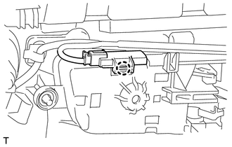
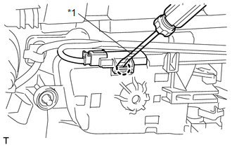
(a) Using a screwdriver, detach the claw and remove the light. HINT: Tape the screwdriver tip before use. Text in Illustration
|
|
(b) Disconnect the connector.
 Luggage Compartment Room Light
Components
COMPONENTS
ILLUSTRATION
Removal
REMOVAL
CAUTION / NOTICE / HINT
HINT:
Use the same procedure for the RH and LH sides.
The procedure listed below is for the LH side. ...
 Personal Light(for Rear Door)
Components
COMPONENTS
ILLUSTRATION
Removal
REMOVAL
CAUTION / NOTICE / HINT
HINT:
Use the same procedure for the RH and LH sides.
The procedure listed below is for the LH side. ...
Other materials about Toyota 4Runner:
Transmitter ID1 Error (C2141/41-C2145/45)
DESCRIPTION
The tire pressure warning valve and transmitters that are installed in the tire
and wheel assemblies measure the air pressure of the tires. The measured values
are transmitted to the tire pressure warning antenna and receiver on the body as
...
Relay
On-vehicle Inspection
ON-VEHICLE INSPECTION
PROCEDURE
1. CHECK STOP LIGHT CONTROL RELAY
(a) Remove the stop light control relay from the engine room relay block.
(b) Measure the resistance according to the value(s) in the table below.
Stan ...

0.0067