Toyota 4Runner: Front Stabilizer Bar(w/o Kdss)
Components
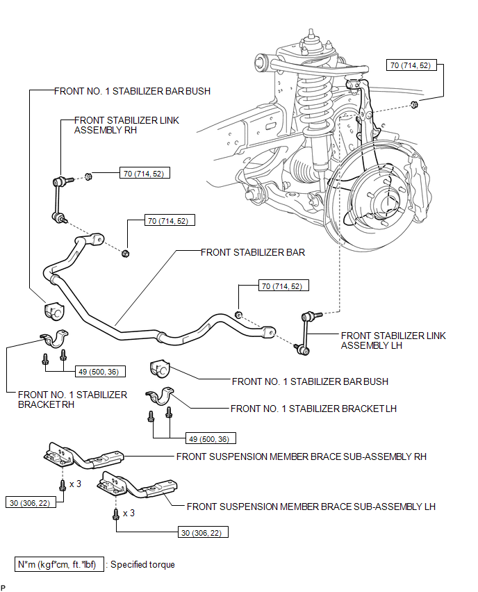
COMPONENTS
ILLUSTRATION
ILLUSTRATION
Inspection
INSPECTION
PROCEDURE
1. INSPECT FRONT STABILIZER LINK ASSEMBLY LH
|
(a) As shown in the illustration, flip the ball joint stud back and forth 5 times. |
|
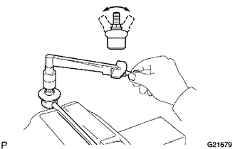
(b) Using a torque wrench, turn the nut continuously at a rate of 3 to 5 seconds per turn and take a torque reading on the 5th turn.
Standard turning torque:
0.05 to 1.96 N*m (0.51 to 20 kgf*cm, 0.44 to 17.3 in.*lbf) or less
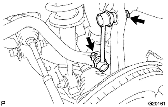
(c) Check for cracks and grease leaks on the ball joint dust cover.
Removal
REMOVAL
PROCEDURE
1. REMOVE FRONT WHEEL
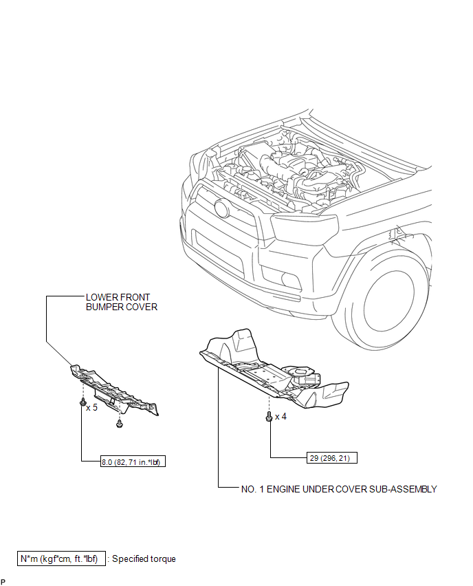
2. REMOVE LOWER FRONT BUMPER COVER
.gif)
3. REMOVE NO. 1 ENGINE UNDER COVER SUB-ASSEMBLY
4. REMOVE FRONT SUSPENSION MEMBER BRACE SUB-ASSEMBLY
5. REMOVE FRONT STABILIZER LINK ASSEMBLY LH
|
(a) Remove the 2 nuts and front stabilizer link assembly LH. HINT: If the ball joint turns together with the nut, use a 6 mm hexagon wrench to hold the stud. |
|
6. REMOVE FRONT STABILIZER LINK ASSEMBLY RH
HINT:
Use the same procedure described for the LH side.
7. REMOVE FRONT NO. 1 STABILIZER BRACKET LH
|
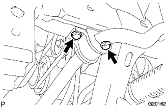
(a) Remove the 2 bolts and front No. 1 stabilizer bracket LH. |
|
8. REMOVE FRONT NO. 1 STABILIZER BRACKET RH
HINT:
Use the same procedure described for the LH side.
9. REMOVE FRONT NO. 1 STABILIZER BAR BUSH
(a) Remove the 2 front No. 1 stabilizer bar bushes.
10. REMOVE FRONT STABILIZER BAR
Installation
INSTALLATION
PROCEDURE
1. INSTALL FRONT STABILIZER BAR
2. INSTALL FRONT NO. 1 STABILIZER BAR BUSH
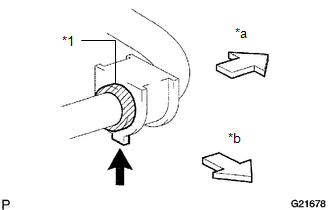
(a) Install the 2 front No. 1 stabilizer bar bushes.
HINT:
- Install the bush to the inner side of the bushing stopper on the stabilizer bar.
- Install the No. 1 stabilizer bush with the protrusion facing inward.
|
*1 |
Bushing Stopper |
|
*a |
Vehicle Outer Side |
|
*b |
Vehicle Front Side |
.png) |
Protrusion |
3. INSTALL FRONT NO. 1 STABILIZER BRACKET LH
(a) Install the front No. 1 stabilizer bracket LH with the 2 bolts.
Torque:
49 N·m {500 kgf·cm, 36 ft·lbf}
4. INSTALL FRONT NO. 1 STABILIZER BRACKET RH
HINT:
Use the same procedure described for the LH side.
5. INSTALL FRONT STABILIZER LINK ASSEMBLY LH
(a) Install the front stabilizer link assembly LH with the 2 nuts.
Torque:
70 N·m {714 kgf·cm, 52 ft·lbf}
HINT:
If the ball joint turns together with the nut, use a 6 mm hexagon wrench to hold the stud.
6. INSTALL FRONT STABILIZER LINK ASSEMBLY RH
HINT:
Use the same procedure described for the LH side.
7. INSTALL FRONT SUSPENSION MEMBER BRACE SUB-ASSEMBLY
.gif)
8. INSTALL NO. 1 ENGINE UNDER COVER SUB-ASSEMBLY
9. INSTALL LOWER FRONT BUMPER COVER
10. INSTALL FRONT WHEEL
Torque:
for aluminum wheel :
103 N·m {1050 kgf·cm, 76 ft·lbf}
for steel wheel :
112 N·m {1142 kgf·cm, 83 ft·lbf}
 Installation
INSTALLATION
PROCEDURE
1. TEMPORARILY INSTALL FRONT STABILIZER LINK ASSEMBLY RH
(a) Temporarily install the front stabilizer link assembly with the bolt.
HINT:
Make sure that the i ...

Other materials about Toyota 4Runner:
Installation
INSTALLATION
PROCEDURE
1. INSTALL REFRESHING SEAT SWITCH
(a) Attach the 4 claws to install the refreshing seat switch.
2. INSTALL LOWER CENTER INSTRUMENT CLUSTER FINISH PANEL SUB-ASSEMBLY
3. INSTALL NO. 2 CONSOLE BOX RETAINER
4. INSTALL UPPER CONSO ...
Speed Sensor
Components
COMPONENTS
ILLUSTRATION
Removal
REMOVAL
PROCEDURE
1. REMOVE SPEED SENSOR NT
(a) Disconnect the sensor connector.
(b) Remove the bolt and sensor.
(c) Remove the O-ring from the sensor.
2. REMOVE SPEED SENSOR SP2
(a) Disconnect th ...

0.0086