Toyota 4Runner: Shift Solenoid "B" Control Circuit Low (Shift Solenoid Valve S2) (P0976,P0977)
DESCRIPTION
Shifting from 1st to 5th is performed in combination with the ON and OFF operation
of the shift solenoid valves SL1, SL2, S1, S2 and SR, which is controlled by the
ECM. If an open or short circuit occurs in one of the shift solenoid valves, the
ECM controls the remaining normal shift solenoid valves to allow the vehicle to
be operated smoothly. In case of an open or short circuit, the ECM stops sending
current to the circuit. For details, refer to the fail-safe chart (See page
.gif) ).
).
|
DTC Code |
DTC Detection Condition |
Trouble Area |
|---|---|---|
|
P0976 |
The ECM detects a short in the solenoid valve S2 circuit 2 times when solenoid valve S2 is operated (1-trip detection logic). |
|
|
P0977 |
The ECM detects an open in the solenoid valve S2 circuit 2 times when solenoid valve S2 is not operated (1-trip detection logic). |
|
MONITOR DESCRIPTION
These DTCs indicate an open or short in the shift solenoid valve S2 circuit. When there is an open or short circuit in any shift solenoid valve circuit, the ECM detects the problem, illuminates the MIL and stores the DTC. When the shift solenoid valve S2 is on, if its resistance is 8 Ω or less, the ECM determines there is a short in the shift solenoid valve S2 circuit.
When the shift solenoid valve S2 is off, if its resistance is 100 kΩ or higher,
the ECM determines there is an open in the shift solenoid valve S2 circuit (See
page ).
MONITOR STRATEGY
|
Related DTCs |
P0976: Shift solenoid valve S2/Range check (Low resistance) P0977: Shift solenoid valve S2/Range check (High resistance) |
|
Required sensors/Components |
Shift solenoid valve S2 |
|
Frequency of operation |
Continuous |
|
Duration |
0.128 sec. or more |
|
MIL operation |
Immediate |
|
Sequence of operation |
None |
TYPICAL ENABLING CONDITIONS
All|
The monitor will run whenever the following DTCs are not stored |
None |
|
Battery voltage |
8 V or higher |
|
Ignition switch |
ON |
|
Starter |
OFF |
|
Shift solenoid valve S2 |
ON |
|
Shift solenoid valve S2 |
OFF |
TYPICAL MALFUNCTION THRESHOLDS
P0976: Range Check (Low Resistance)|
Shift solenoid valve S2 resistance |
8 Ω or less |
|
Shift solenoid valve S2 resistance |
100 kΩ or higher |
COMPONENT OPERATING RANGE
|
Shift solenoid valve S2 resistance |
11 to 15 Ω at 20°C (68°F) |
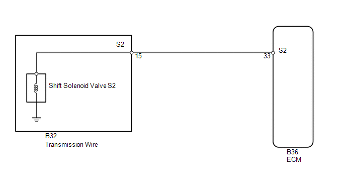
WIRING DIAGRAM
CAUTION / NOTICE / HINT
NOTICE:
Perform the universal trip to clear permanent DTCs (See page
).
HINT:
The shift solenoid valve S2 turns ON/OFF normally when the shift lever is in D.
|
ECM gear shift command |
1st |
2nd |
3rd |
4th |
5th |
|
Shift solenoid valve S2 |
OFF |
ON |
ON |
OFF |
OFF |
PROCEDURE
|
1. |
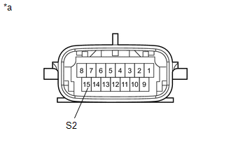
INSPECT TRANSMISSION WIRE (SHIFT SOLENOID VALVE S2) |
|
(a) Disconnect the B32 transmission wire connector. |
|
(b) Measure the resistance according to the value(s) in the table below.
Standard Resistance:
|
Tester Connection |
Condition |
Specified Condition |
|---|---|---|
|
15 (S2) - Body ground |
20°C (68°F) |
11 to 15 Ω |
|
*a |
Component without harness connected (Transmission Wire) |
| NG | .gif) |
GO TO STEP 3 |
|
.gif)
|
2. |
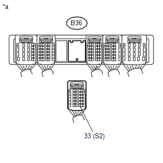
CHECK HARNESS AND CONNECTOR (TRANSMISSION WIRE - ECM) |
|
(a) Disconnect the B36 ECM connector. |
|
(b) Measure the resistance according to the value(s) in the table below.
Standard Resistance:
|
Tester Connection |
Condition |
Specified Condition |
|---|---|---|
|
B36-33 (S2) - Body ground |
20°C (68°F) |
11 to 15 Ω |
|
*a |
Rear view of wire harness connector (to ECM) |
| OK | |
REPLACE ECM |
| NG | |
REPAIR OR REPLACE HARNESS OR CONNECTOR |
|
3. |
INSPECT SHIFT SOLENOID VALVE S2 |
| OK | |
REPAIR OR REPLACE TRANSMISSION WIRE |
| NG | |
REPLACE SHIFT SOLENOID VALVE S2 |
 Shift Solenoid "E" Control Circuit Low (Shift Solenoid Valve SR) (P0985,P0986)
DESCRIPTION
Shifting from 1st to 5th is performed in combination with the ON and OFF operation
of the shift solenoid valves SL1, SL2, S1, S2 and SR, which is controlled by the
ECM. If an open or ...
 1-2 Shift (1-2 Shift Valve) (P0781)
DESCRIPTION
The 1-2 shift valve performs shifting to 1st gear and other gears.
DTC Code
DTC Detection Condition
Trouble Area
P0781
Gear r ...
Other materials about Toyota 4Runner:
Problem Symptoms Table
PROBLEM SYMPTOMS TABLE
NOTICE:
After replacing the navigation receiver assembly of vehicles subscribed to pay-type
satellite radio broadcasts, registration of the XM radio ID is necessary.
HINT:
Use the table below to help determine the cause of ...
Removal
REMOVAL
CAUTION / NOTICE / HINT
HINT:
Use the same procedure for the RH and LH sides.
The procedure listed below is for the LH side.
PROCEDURE
1. REMOVE FRONT WHEEL
2. REMOVE SKID CONTROL SENSOR WIRE
3. REMOVE FRONT SUSPENSION UPPER ...

0.028